Aqara Empowerment Communication Protocol
Chatper 1 Introduction
This document defines the Aqara Empowerment Communication Protocol (AECP), a complete protocol stack for data exchange over UART between a wireless communication empowerment module (which may run different IoT wireless protocol stacks, hereafter referred to as the "Client") and a host MCU (hereafter referred to as the "Server").
The Client implements IoT wireless protocol access and empowerment functions, and is responsible for network management, cloud communication, and IoT protocol adaptation. The Server executes the product's own business logic and is not aware of the wireless network. All state synchronization, Commands delivery, and event notification between the two sides are carried by this protocol.
This protocol continues to evolve. Version iteration follows the principle of forward compatibility, but full compatibility with very old firmware or firmware that has not been maintained for a long time is not guaranteed. The following recommendations apply to all integrators:
- Use the documentation of the specific module actually used as the source of truth.
- Consult official Aqara support, or use the latest officially recommended public firmware.
Scope
This specification covers:
- UART Hardware Interface requirements between Client and Server (see Chapter 2)
- Data Types, data frame encoding, and application Interaction formats (see Chapter 3)
- Power-on initialization flow, including Link Establishment, Profile Discovery, Server data sync, and Wake Signaling (see Chapter 4)
- Profile model, Response, retry, and related implementation rules (see Chapter 5)
- Attributes and Commands definitions for the Foundation Profile and product Profiles (see Chapter 6 and Chapter 7)
- Firmware online upgrade (OTA) sub-protocol (see Chapter 6 Foundation Profile)
- Serial message encoding and decoding examples (see Appendix A)
This specification is intended for embedded firmware developers and provides the technical details required for interoperability.
Protocol Architecture and Design Principles
This section introduces the overall architecture, Design Principles, and core concepts of AECP so that readers have a consistent frame of reference before reading the detailed technical chapters.
System Architecture
AECP targets a dual-chip cooperation scenario consisting of a "wireless empowerment module + host MCU". The wireless empowerment module handles IoT wireless protocol access, pairing, network connection, and cloud communication, hiding the complexity of the wireless network from the host MCU. The host MCU focuses on the product's own business logic and peripheral control. The two sides are connected through a UART serial interface, and this protocol defines all data exchange rules on that link.
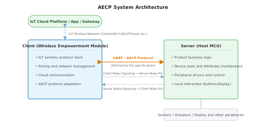
In this protocol, the wireless empowerment module acts as the Client, and the host MCU acts as the Server. These role names are based on "ownership of data and capabilities": the device's business state and capabilities are owned and provided by the MCU (Server), while the module (Client) accesses and empowers those capabilities. This convention applies throughout the specification and is the basis for understanding later Attributes ownership and Interaction Direction rules.
UART Buffer Constraints
The Client module's UART receive buffer size and transmit buffer size SHALL each be no less than 1024 bytes. Both sides SHALL exchange UART buffer capability during link establishment (see Link Establishment) and SHALL use the smaller of the two declared values as the negotiated UART buffer size to constrain subsequent AECP single-frame lengths. Each side's declared value SHALL NOT be less than 1024 bytes; therefore the negotiated result SHALL NOT be less than 1024 bytes. The complete AECP frame length is calculated from SOF through Overall Checksum, including the frame header, Data Segment, and checksum fields.
| Receive buffer size | Transmit buffer size | Notes |
|---|---|---|
| Minimum 1024 bytes | Minimum 1024 bytes | If the firmware version supports file transfer functions, the maximum buffer size is determined by the maximum single-packet file data length used during file transfer. |
If the complete AECP frame length exceeds the negotiated UART buffer size, receive overflow, packet loss, or parsing failure may occur. When designing attribute reports, command parameters, and IAP OTA fragment lengths, implementers SHALL use the negotiated UART buffer size as the upper limit for a single-frame length. This constraint applies only to AECP communication frames defined by this protocol, and does not apply to the firmware transfer process carried by XMODEM during BootLoader OTA.
Design Principles
This protocol is designed according to the following principles:
- Decoupled responsibilities: The Server is not aware of the wireless network, and the Client does not participate in product business logic. Evolution or replacement on either side, such as changing the wireless protocol, should not affect the other side.
- Attributes-centered data model: Device state and capabilities are uniformly abstracted as Attributes (Attribute). State synchronization is reduced to reading, writing, and reporting Attributes, making the data model clear, enumerable, and verifiable.
- Core + product layered Profile model: All devices share a mandatory Foundation Profile that provides common capabilities, while a single product Profile describes the specific product category, balancing consistency and extensibility.
- Symmetric Interaction model: Attribute access is organized around "who owns it, who initiates it, and whether it is pulled or pushed", forming a symmetric and closed set of Operation Codes that avoids special cases and reduces implementation complexity.
- Evolvability and forward compatibility: Protocol version numbers and optional declarations for Profiles and Attributes support gradual capability expansion while preserving forward compatibility with older implementations.
Layered Model
Logically, AECP can be divided into four layers. From bottom to top, each layer has independent responsibilities and encapsulates the layer below:
| Layer | Responsibility | Corresponding Sections |
|---|---|---|
| Physical Layer | UART electrical characteristics and timing, Wake Pin and Wake Signaling | Chapter 2, Chapter 4 |
| Frame Layer | Frame structure, field encoding, byte order, HCS, and CRC checks | Chapter 3 |
| Transaction Layer | Operation Code semantics, request and Response pairing, Seq correlation, timeout, and retry | Chapter 3, Chapter 5 |
| Application Layer | Attributes, Commands, Profiles, and OTA sub-protocols | Chapter 5, Chapter 6, Chapter 7 |
Core Concepts and Interaction Model
The following core concepts are required to understand this protocol:
- Roles (Client / Server): The Client is the wireless empowerment module, and the Server is the host MCU. Their responsibilities and ownership are described in System Architecture.
- Profile: A functional domain consisting of related Attributes and Commands, identified by a Profile ID. The Server supports the Foundation Profile (
0x0000) by default and declares a single product Profile throughProductProfileID. - Attributes (Attribute): Data units representing device state or capabilities. They are classified by owner as Server Attributes (
Side = S) or Client Attributes (Side = C), and their valid operations are declared by Access. - Commands (Command): Triggered actions. The valid Initiator and Response method are declared in the Commands table of the owning Profile.
- Frames and transactions: Each Interaction is carried by a data frame. The Operation Code (OPC) defines the message type and Direction, and Seq correlates a request with its Response to form one transaction.
Attributes Interaction follows a symmetric and closed set of operations. Centered on the Attributes owner, it distinguishes the two dimensions of "pull by accessor" and "push by owner", resulting in the complete operation set shown below. For detailed encoding and timing, see Chapter 3:
| Interaction | Initiator | Target | Initiating Operation Code | Response |
|---|---|---|---|---|
| Read Server Attributes | Client | Server Attributes | READ | READ_RESPONSE |
| Write Server Attributes | Client | Server Attributes | WRITE | WRITE_RESPONSE |
| Server-initiated report | Server | Server Attributes | REPORT | ACKNOWLEDGE |
| Query Client Attributes | Server | Client Attributes | QUERY | QUERY_RESPONSE |
| Client-initiated notification | Client | Client Attributes | NOTIFY | ACKNOWLEDGE |
| Trigger Commands | As defined by the Commands table | Commands | COMMAND | ACKNOWLEDGE / paired COMMAND / None |
Terms and Definitions
| Term | Definition |
|---|---|
| Client | Wireless communication empowerment module. It runs an IoT wireless protocol stack and is responsible for IoT protocol access and empowerment functions. In AECP, it initiates READ/WRITE and Commands (COMMAND) for Server Attributes, responds to Server queries for Client Attributes (QUERY_RESPONSE), and may proactively report Client Attributes (NOTIFY). |
| Server | Host microcontroller (MCU) that executes product business logic. In AECP, it owns device-side state, responds to Client reads, writes, and Commands for Server Attributes, proactively reports Attributes (REPORT), and may initiate Attribute queries (QUERY) to the Client. The Server is not aware of the wireless network. |
| Profile | Functional domain. A Profile consists of related Attributes and Commands and is identified by a Profile ID (uint16). The Server supports the Foundation Profile (0x0000) by default and declares a single product Profile through ProductProfileID. |
| Attributes (Attribute) | Persistent data unit representing device state or capabilities, uniquely identified within its Profile by Attribute ID (uint16). The full Attributes address is determined by Profile ID + Attribute ID. Each Attribute has a defined Data Type, Side (C or S), Access, and implementation requirement (Conformance). READ/WRITE/QUERY/QUERY_RESPONSE/REPORT/NOTIFY all operate on Attributes. |
| Commands (Command) | Triggered action, identified by Command ID (uint16), with typed parameters. The valid Initiator for each Command is explicitly declared by Direction in the Commands table of the owning Profile. The receiver responds with ACKNOWLEDGE or a paired COMMAND. |
| Operation Code (OPC) | A 1-byte field in the data frame that identifies the message type and Direction. AECP defines 10 Operation Codes corresponding to the Interaction Model for Attributes read/write, Attributes report, Attributes query, Attributes notification (NOTIFY), and Commands. |
| Side | Attributes ownership marker. C (Client) = the Attribute is owned and maintained by the Client; S (Server) = the Attribute is owned and maintained by the Server. Each Attribute SHALL be explicitly marked C or S in the Attributes table. |
| Conformance | Implementation requirement marker. M (Mandatory) = the item SHALL be implemented; O (Optional) = the item MAY be implemented. |
| Profile ID | A 2-byte field in the data frame header (formerly Device Type) that identifies the functional domain to which the frame belongs, rather than only distinguishing product type. |
| OTA | Over-The-Air firmware online upgrade. This protocol defines two Upgrade Methods: IAP OTA and BootLoader OTA. |
| Wake Pin | Hardware pin, active low. Client and Server each provide one for the peer to pull low during Wake Signaling. See Chapter 2. |
| Wake Signaling | The complete process before UART communication: active-low assertion on the peer's Wake Pin, T0 wait, UART transfer, and pin release. See Wake Ssignaling. |
| Link Establishment | The first AECP interaction after power-on. Client sends LinkEstablishmentRequest(ClientUartBufferSize); Server returns LinkEstablishmentResponse(LowPowerFeature, ServerUartBufferSize). See Link Establishment. |
| Profile Discovery | The process in which Client READs Server Profiles and attribute initial values; Client sends ProfileDiscoveryComplete when done. See Profile Discovery. |
| LowPowerFeature | Parameter in LinkEstablishmentResponse; negotiates Wake Signaling enablement; enabled by default before negotiation; Normal means negotiation disables it. See LowPowerFeature. |
Abbreviations
| Abbreviations | Full Name |
|---|---|
| ACK | Acknowledgement (Response) |
| ASCII | American Standard Code for Information Interchange |
| CRC | Cyclic Redundancy Check |
| GPIO | General-Purpose Input/Output |
| IAP | In Application Programming |
| ISP | In System Programming |
| LSB | Least Significant Byte / Bit |
| MCU | Micro Controller Unit |
| MSB | Most Significant Byte / Bit |
| OTA | Over-The-Air |
| SOF | Start Of Frame (Start of Frame) |
| UART | Universal Asynchronous Receiver-Transmitter |
| UTC | Coordinated Universal Time |
| XMODEM | XMODEM file transfer protocol |
Document Conventions
Keyword Conventions
The keywords in this document are interpreted according to RFC 2119:
- SHALL — absolute requirement.
- SHALL NOT — absolute prohibition.
- SHOULD — recommended behavior; the impact needs to be fully understood and weighed before ignoring it.
- SHOULD NOT — discouraged behavior; the impact needs to be fully understood and weighed before adopting it.
- MAY — optional item.
Byte Order Convention
All multi-byte fields in AECP are transmitted in Big-Endian order, meaning the most significant byte is sent first. This rule applies to the frame header, Data Segment, Attributes values, Commands parameters, and Overall Checksum.
The following fields explicitly use Big-Endian order: Profile ID, Data Length, and Overall Checksum.
The only exception is the OTA Header inside the OTA firmware file. The OTA Header is not a field of an AECP communication frame. Its internal fields use Little-Endian order, as described separately in the firmware upgrade chapter.
Numeric Notation Convention
- Hexadecimal values use the
0xprefix, for example,0x55. - Binary values use the
0bprefix, for example,0b00000001. - Byte lengths use
N bytes, for example,2 bytes.
Field Notation Convention
Attributes tables, Commands tables, and parameter tables in this specification SHALL use the column meanings defined below. Later chapters do not repeat these column definitions.
| Column | Meaning |
|---|---|
ID / Attribute ID / Command ID | Item identifier. In an Attributes table it indicates Attribute ID; in a Commands table it indicates Command ID. |
Name / Name | Item name, using an English identifier. |
Type / Type | Data Type. Values SHALL come from the Data Types chapter or the Data Types defined by the corresponding Profile. |
Constraint / Constraint | Numeric value range, length, fixed value, or value constraint. "No additional constraints" means only the base Data Type constraints apply. |
Default / Default | Default value or initial value after reset. - means no unified Default is specified. |
Access / Access | Valid access methods. R = READ; W = WRITE; RP = REPORT; Q = QUERY; NF = NOTIFY. |
Side / Side | Attributes ownership marker. C = owned and maintained by the Client; S = owned and maintained by the Server. |
Conformance / Conformance | Implementation requirement. M = Mandatory, SHALL be implemented; O = Optional, MAY be implemented. |
Direction / Direction | Valid Commands Initiator, as defined by the Commands table. |
Response / Response | Commands Response method. It may be ACKNOWLEDGE, a paired COMMAND name, or N (no Response). |
Description / Description / Description | Brief description of the item. |
Order / Parameter Order | Sequence number of the parameter in the Data Segment immediately after Cmd ID, starting from 1; lower numbers are encoded first. This number defines order only and is not an on-wire field. |
Parameter Details / Parameters | Parameter definition table for a COMMAND: lists Parameter Order, Name, Type, Constraint, and Default. Raw Data length is determined by Type (see Data Types Overview). Encoding rules are defined in COMMAND (OPC = 0x9). |
Chapter 2 Hardware Interface
This chapter defines the UART serial Hardware Interface requirements between the Client and the Server.
UART Communication Parameters
Serial communication between the Client and the Server shall use the following parameters:
| Parameter | Value |
|---|---|
| Baud Rate (Baud Rate) | 115200 bps |
| Data Bits (Data Bits) | 8 bits |
| Parity (Parity) | None (None) |
| Stop Bits (Stop Bits) | 1 bits |
| Flow Control (Flow Control) | None (None) |
| Supply Voltage | DC 3.3 V (used by both Client and Server) |
Pin Connections
At least the following connections are required between Client and Server:
- TXD / RXD: Serial data lines. Client TXD connects to Server RXD, and Client RXD connects to Server TXD, using a cross connection.
- wake pin (Wake Pin): Bidirectional wake-up signal for low-power devices (Wake Signaling uses this pin; see Wake Signaling). The Client and the Server each provide one wake pin so that each side can be woken by the other side.
- BootLoader Entry GPIO: If the device declares support for BootLoader OTA, it SHALL provide a hardware entry path controlled by the Client so that the Server can enter BootLoader through a GPIO, reset pin, or Boot selection pin.
- Power (VCC / GND): Both Client and Server use DC 3.3 V power and share a common ground.
Specific pin numbers vary by Client product model. Refer to the corresponding Client hardware specification or contact official Aqara support for accurate pin definitions.
Electrical Characteristics
- The logic level of all digital I/O pins (TXD, RXD, wake pin, and BootLoader Entry GPIO) is 3.3 V CMOS.
- Avoid direct connection to 5 V logic systems. If Server is a 5 V system, a level-shifting circuit is required.
Chapter 3 Data Types and Interaction Format
This chapter first defines the AECP application interaction model and frame structure, then defines Data Segment and checksum encoding rules, and finally defines Data Type and Status. Specific Attributes, Commands, enumerations, and value ranges are defined by each Profile.
Interaction Model
This section defines the AECP on-wire data frame format, Operation Code semantics, transaction matching rules, and application-layer interaction model. Specific Attributes, Commands, enumerations, and value ranges are defined by each Profile.
Frame Structure Overview
An AECP complete frame consists of a fixed header (8 bytes), a variable-length Data Segment, and a fixed trailing CRC checksum (2 bytes). Excluding the Data Segment, the fixed overhead is 10 bytes.
+-------+------------+-------+-------+---------+-------+------------------+-------+
|  SOF  | Profile ID |  Seq  |  OPC  |  D-Len  |  HCS  |   Data Segment   |  CRC  |
| (1 B) |    (2 B)   | (1 B) | (1 B) |  (2 B)  | (1 B) |     (N bytes)    | (2 B) |
+-------+------------+-------+-------+---------+-------+------------------+-------+
| Abbreviations | Length | Description |
|---|---|---|
| SOF | 1 byte | Start Of Frame, the frame start marker, fixed to 0x55. |
| Profile ID | 2 bytes | Functional Profile Identifier, Big-Endian. The receiver interprets the frame semantics by combining Profile ID with Attribute ID or Command ID. |
| Seq | 1 byte | Sequence, the transaction sequence number, used for response matching, retransmission deduplication, and transaction association. |
| OPC | 1 byte | Operation Code, which defines the message type, direction, and Data Segment format. |
| D-Len | 2 bytes | Data Length, the byte length of the Data Segment, Big-Endian. |
| HCS | 1 byte | Header Checksum, the last byte of the frame header; checksum over the 7 bytes from SOF through D-Len. |
| - | N bytes | Data Segment, whose format is determined by OPC; N = D-Len. |
| CRC | 2 bytes | Overall Checksum, CRC16-Modbus, covering the Data Segment, Big-Endian. |
Profile ID, D-Len, and CRC all use Big-Endian encoding, with the most significant byte first.
Frame Header Field Descriptions
SOF - Start of Frame
SOF is fixed to 0x55 and identifies the start of a frame. The receiver SHALL use 0x55 as the frame synchronization marker.
Profile ID - Functional Profile Identifier
Profile ID is a 2-byte Big-Endian unsigned integer that identifies the Functional Profile to which this frame belongs. The receiver SHALL combine Profile ID with Attribute ID or Command ID to fully interpret the frame semantics.
| Profile ID | Description |
|---|---|
0x0000 | Foundation Profile. All devices SHALL support it. It includes basic Attributes, basic Commands, and firmware upgrade capabilities. |
0x1000 | Thermostat Profile. It includes thermostat-specific Attributes and Commands. |
The Server SHALL support Foundation Profile (0x0000) by default and declare the unique product Profile through ProductProfileID in Foundation Profile. The Client may switch Profile ID between Foundation Profile and the product Profile according to the current interaction target.
Seq - Transaction Sequence Number
Seq is a 1-byte unsigned integer used to associate request frames with response frames and to support retransmission detection:
- Client and Server each maintain an independent sequence number counter; the counters are not synchronized.
- The sender SHALL increment the sequence number for each new transaction, wrapping back to
0x00after overflow. - The Seq of a response frame SHALL match the Seq of the request frame to which it responds.
- When a receiver receives a retransmitted frame with the same Seq and the same payload, it SHOULD process it idempotently and return a response with the same semantics.
OPC - Operation Code
OPC is 1 byte and defines the message type, direction, and target of the frame:
| Value | Name | Direction | Target | Semantics |
|---|---|---|---|---|
| 0x1 | READ | Client -> Server | Attributes | Client reads Attributes on the Server. |
| 0x2 | READ_RESPONSE | Server -> Client | Attributes | Server responds to READ and carries per-Attribute Status and Attribute values. |
| 0x3 | WRITE | Client -> Server | Attributes | Client writes Server Attributes. |
| 0x4 | WRITE_RESPONSE | Server -> Client | Attributes | Server responds to WRITE and carries per-Attribute Status. |
| 0x5 | REPORT | Server -> Client | Attributes | Server proactively reports Attribute changes or periodic Attribute values. |
| 0x6 | ACKNOWLEDGE | Receiver -> original Initiator | Frame | Provides frame-level acknowledgement for REPORT, NOTIFY, or COMMAND that does not need to return data. |
| 0x7 | QUERY | Server -> Client | Attributes | Server queries and reads Attributes on the Client. |
| 0x8 | QUERY_RESPONSE | Client -> Server | Attributes | Client responds to QUERY and carries per-Attribute Status and Attribute values. |
| 0x9 | COMMAND | Determined by Command definition | Commands | Initiates a triggering Command and carries Command ID and typed parameters. |
| 0xA | NOTIFY | Client -> Server | Attributes | Client proactively reports its own Attribute changes or synchronizes Attribute values. |
Except for 0x9 (COMMAND), all OPC values are Attribute operations and the Data Segment contains Attribute ID. OPC 0x9 is a Command operation and the Data Segment contains Command ID.
D-Len - Data Length
D-Len is a 2-byte Big-Endian unsigned integer that represents the byte length of the Data Segment. When the Data Segment is empty, D-Len = 0.
When constructing any AECP frame, the sender SHALL ensure that the complete frame length does NOT exceed the UART buffer size negotiated during link establishment. The complete frame length is calculated as follows:
Complete Frame Length = 10 + D-Len
The fixed overhead of 10 bytes equals the 8-byte frame header (SOF through HCS) plus the 2-byte Overall Checksum. The negotiated UART buffer size SHALL be min(ClientUartBufferSize, ServerUartBufferSize). Each side's declared value SHALL NOT be less than 1024 bytes; the negotiated result SHALL NOT be less than 1024 bytes. See Link Establishment for negotiation rules. See UART Buffer Constraints for UART buffer requirements.
HCS - Header Checksum
HCS is 1 byte and is the last byte of the frame header. Its checksum range covers the 7 bytes from SOF through D-Len, inclusive, and is used to verify header integrity.
Calculation method (two's-complement sum):
Sum = SOF + Profile_ID[MSB] + Profile_ID[LSB]
    + Seq + OPC + D-Len[MSB] + D-Len[LSB]

HCS = (~Sum + 1) & 0xFF
CRC (Overall Checksum) uses a different checksum algorithm. See Overall Checksum.
Application Interaction Model
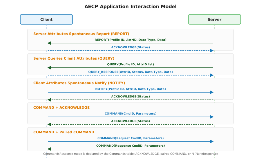
AECP divides application interactions into four categories: Server Attribute read/write, Server Attribute reporting, Client Attribute query/reporting, and Command interaction. In Profile Attribute tables, Side and Access determine whether an Attribute supports the corresponding operation, and Conformance determines whether the Attribute must be implemented. In Profile Command tables, Direction determines the legal Initiator of a Command.
Roles, Addressing, and Attribute Ownership
Complete application addressing is formed by the frame header Profile ID together with Attribute ID or Command ID in the Data Segment:
Profile ID + Attribute IDuniquely identifies an Attribute.Profile ID + Command IDuniquely identifies a Command.- Attributes with
Side = Sare owned by the Server. The Client may perform READ / WRITE according toAccess, and the Server may perform REPORT according toAccess. - Attributes with
Side = Care owned by the Client. The Server may perform QUERY according toAccess(the Client returns Attribute values through QUERY_RESPONSE), and the Client may proactively synchronize Attribute values through NOTIFY according toAccess.
Attribute Read and Write
Attribute read and write operations allow the Client to access Attributes owned by the Server.
| Transaction | Response | Description |
|---|---|---|
| READ | READ_RESPONSE | Client reads Attributes with Side = S and Access containing R. |
| WRITE | WRITE_RESPONSE | Client writes Attributes with Side = S and Access containing W. |
The Status in READ_RESPONSE and WRITE_RESPONSE is a per-Attribute result. When a single frame contains multiple Attribute Blocks, each Attribute succeeds or fails independently; failure of one Attribute does not affect processing of other Attributes in the same frame.
Attribute Reporting and Acknowledgement
REPORT is used by the Server to proactively report Attribute changes or periodic Attribute values. Only Attributes with Side = S and Access containing RP may be reported through REPORT.
The Status in ACKNOWLEDGE is a frame-level result, indicating whether the receiver successfully received and accepted the REPORT frame. If a REPORT frame carries multiple Attribute Blocks, ACKNOWLEDGE does not return per-Attribute results.
Reporting behavior is declared by the Profile Attribute table:
RPindicates that the Server is capable of proactively reporting the Attribute.- For any readable Attribute with
Side = SandAccesscontainingR,AccessSHALL also containRP. - Change reporting, periodic reporting, associated reporting, and similar policies are defined by the specific Profile Attribute descriptions.
- This protocol does not define separate reporting-configuration Commands. Runtime configuration SHOULD be performed through the corresponding Server Attributes.
Client Attribute Query, Response, and Reporting
QUERY / QUERY_RESPONSE are used by the Server to read Attributes owned by the Client on demand.
Only Attributes with Side = C and Access containing Q may be queried. The Status in QUERY_RESPONSE is a per-Attribute result, and the truncation rules are the same as READ_RESPONSE.
NOTIFY is used by the Client to proactively synchronize its own Attributes to the Server, especially when Attribute values change. Only Attributes with Side = C and Access containing NF may be reported through NOTIFY. After receiving NOTIFY, the Server SHALL return ACKNOWLEDGE. Its Status is a frame-level result, indicating whether the NOTIFY frame was successfully received and accepted. If a NOTIFY frame carries multiple Attribute Blocks, ACKNOWLEDGE does not return per-Attribute results.
Reporting behavior is declared by the Profile Attribute table:
NFindicates that the Client is capable of proactively issuing NOTIFY for the Attribute.- Change reporting, periodic reporting, and similar policies are defined by the specific Profile Attribute descriptions.
- This protocol does not define separate NOTIFY configuration Commands. Runtime configuration SHOULD be performed through the corresponding Attributes.
Command Interaction and Response Modes
COMMAND is used to trigger an action. Command semantics are determined by Profile ID + Command ID; the legal Initiator is determined by the Direction of the Command in its Profile Command table; and the response mode is determined by the Response field in the Command table.
In the timing diagrams below, Initiator indicates the COMMAND initiator allowed by the Command Direction, and Receiver indicates the other endpoint that receives the COMMAND.
After receiving a COMMAND, the receiver SHALL choose one of the following response paths according to the Command table's Response value:
- If
Response = ACKNOWLEDGE, the receiver SHALL directly return ACKNOWLEDGE. - If
Response = <CommandName>, the receiver SHALL return the paired COMMAND corresponding to that name. - If
Response = N, the receiver SHALL return no response.NSHOULD be used only for paired return Commands to avoid an infinite response chain.
Commands that return no data use ACKNOWLEDGE for direct acknowledgement.
Commands that need to return data use a paired COMMAND to return the data. Whether the paired COMMAND itself receives a further response is determined by its own Response declaration.
If a paired return Command declares Response = ACKNOWLEDGE, the original Initiator SHALL return ACKNOWLEDGE after receiving the paired COMMAND. If it declares Response = N, the original Initiator SHALL return no further response.
If the receiver cannot execute the Command, it SHOULD directly return ACKNOWLEDGE with a non-zero Status error code and SHALL NOT send the paired COMMAND.
Transactions, Directions, and Sequence Numbers
The Seq of a transaction response SHALL match the Seq of the original transaction:
| Request / Active Frame | Response Frame | Seq Rule |
|---|---|---|
| READ | READ_RESPONSE | The response reuses the Seq of READ. |
| WRITE | WRITE_RESPONSE | The response reuses the Seq of WRITE. |
| REPORT | ACKNOWLEDGE | ACKNOWLEDGE reuses the Seq of REPORT. |
| QUERY | QUERY_RESPONSE | QUERY_RESPONSE reuses the Seq of QUERY. |
| NOTIFY | ACKNOWLEDGE | ACKNOWLEDGE reuses the Seq of NOTIFY. |
| COMMAND | ACKNOWLEDGE, paired COMMAND, or no response | ACKNOWLEDGE or the paired COMMAND reuses the Seq of COMMAND; no response frame is sent when Response = N. |
REPORT and Server-initiated COMMAND are Server-originated transactions, and the Server uses a new local Seq. Client-initiated READ, WRITE, COMMAND, and NOTIFY are Client-originated transactions, and the Client uses a new local Seq.
Status Usage
Status encoding is defined in Status. Status has different scopes in different OPC values:
| Frame Type | Status Scope | Description |
|---|---|---|
| READ_RESPONSE / QUERY_RESPONSE | Per-Attribute | Each Attribute Block carries an independent Status. |
| WRITE_RESPONSE | Per-Attribute | Each Attribute Block carries an independent Status. |
| ACKNOWLEDGE | Frame-level | Confirms the receive / execution result for the entire REPORT, NOTIFY, or COMMAND frame. |
When a per-Attribute Status is not 0x00, the corresponding Attribute Block SHALL contain only Attribute ID and Status, and SHALL NOT carry Data Type or Data.
Encoding Rules
Data Segment Encoding Rules
This section defines the Data Segment layout corresponding to each OPC. When multiple Attributes are present, their Attribute Blocks are placed contiguously in sequence.
Every Data Segment layout in this section SHALL follow UART buffer constraints. When filling Attribute Blocks, Command parameters, or variable-length Raw Data, the sender SHALL ensure that 10 + D-Len does NOT exceed the UART buffer size negotiated during link establishment (the smaller of the two declared values, which SHALL NOT be less than 1024 bytes). If the content to be sent cannot fit in a single frame, the sender SHALL use the fragmentation, paging, or repeated interaction mechanism defined by the corresponding Profile, and SHALL NOT directly send a frame that exceeds buffer capacity.
READ (OPC = 0x1)
READ requests one or more Server Attributes. The Data Segment contains only an Attribute ID list and carries no value.
Data Segment (one or more AttrIDs):
+-----------+-----------+-----+-----------+
|  AttrID 1 |  AttrID 2 | ... |  AttrID N |
|   (2 B)   |   (2 B)   |     |   (2 B)   |
+-----------+-----------+-----+-----------+
READ_RESPONSE (OPC = 0x2)
READ_RESPONSE responds to READ. The Data Segment SHALL return one Attribute Block for each Attribute ID in the READ request, and the Attribute Block order SHOULD match the Attribute ID order in the READ request.
Each Attribute Block independently carries per-Attribute Status:
- If Status =
0x00, the Attribute was read successfully and the Attribute Block SHALL also carry Data Type and Data. - If Status !=
0x00, the Attribute read failed and the Attribute Block SHALL carry only AttrID and Status, and SHALL NOT carry Data Type or Data. - In a multi-Attribute READ, some Attributes may succeed and others may fail. Failure of one Attribute SHALL NOT affect returns for other Attributes in the same frame.
Data Segment (single Attribute, Status = 0x00):
+--------+--------+-----------+------+
| AttrID | Status | Data Type | Data |
| (2 B)  | (1 B)  |   (1 B)   |(N B) |
+--------+--------+-----------+------+
Data Segment (single Attribute, Status != 0x00):
+--------+--------+
| AttrID | Status |
| (2 B)  | (1 B)  |
+--------+--------+
Example where all Attributes succeed:
+---------+--------+-----------+-------+---------+--------+-----------+-------+
| AttrID1 | Status | Data Type | Data1 | AttrID2 | Status | Data Type | Data2 |
| (2 B)   | (1 B) |   (1 B)   | (N B) | (2 B)   | (1 B) |   (1 B)   | (N B) |
+---------+--------+-----------+-------+---------+--------+-----------+-------+
Example where some Attributes succeed:
+---------+--------+-----------+-------+---------+--------+
| AttrID1 | Status | Data Type | Data1 | AttrID2 | Status |
| (2 B)   | (1 B) |   (1 B)   | (N B) | (2 B)   | (1 B) |
+---------+--------+-----------+-------+---------+--------+
In the example above, AttrID1 is read successfully. AttrID2 fails to read, so no Data Type or Data follows AttrID2.
Example where all Attributes fail:
+---------+--------+---------+--------+
| AttrID1 | Status | AttrID2 | Status |
| (2 B)   | (1 B) | (2 B)   | (1 B) |
+---------+--------+---------+--------+
WRITE (OPC = 0x3)
WRITE writes Server Attributes. The Data Segment consists of one or more Attribute Blocks, and each Attribute Block carries Attribute ID, Data Type, and Data.
Data Segment (single Attribute):
+--------+-----------+------+
| AttrID | Data Type | Data |
| (2 B)  |   (1 B)   |(N B) |
+--------+-----------+------+
WRITE_RESPONSE (OPC = 0x4)
WRITE_RESPONSE responds to WRITE. The Data Segment consists of one or more Attribute Blocks, and each Attribute Block carries per-Attribute Status.
Data Segment (single Attribute):
+--------+--------+
| AttrID | Status |
| (2 B)  | (1 B)  |
+--------+--------+
REPORT (OPC = 0x5)
REPORT proactively reports one or more Server Attributes. The Data Segment format is the same as WRITE and consists of one or more Attribute Blocks.
Data Segment (single Attribute, same as WRITE):
+--------+-----------+------+
| AttrID | Data Type | Data |
| (2 B)  |   (1 B)   |(N B) |
+--------+-----------+------+
ACKNOWLEDGE (OPC = 0x6)
ACKNOWLEDGE provides frame-level acknowledgement for REPORT, NOTIFY, or COMMAND. The Data Segment contains only Status.
Data Segment:
+--------+
| Status |
| (1 B)  |
+--------+
QUERY (OPC = 0x7)
QUERY reads one or more Client Attributes. The Data Segment format is the same as READ.
Data Segment (one or more AttrIDs):
+-----------+-----------+-----+-----------+
|  AttrID 1 |  AttrID 2 | ... |  AttrID N |
|   (2 B)   |   (2 B)   |     |   (2 B)   |
+-----------+-----------+-----+-----------+
QUERY_RESPONSE (OPC = 0x8)
QUERY_RESPONSE responds to QUERY. The Data Segment format is the same as READ_RESPONSE, and it SHALL also return one Attribute Block for each Attribute ID in QUERY.
QUERY_RESPONSE also supports the cases where all Attributes succeed, some Attributes succeed, or all Attributes fail. An Attribute Block with Status = 0x00 carries Data Type and Data. An Attribute Block with Status != 0x00 carries only AttrID and Status.
NOTIFY (OPC = 0xA)
NOTIFY is used by the Client to proactively report one or more Client Attributes. The Data Segment format is the same as REPORT and consists of one or more Attribute Blocks.
Data Segment (single Attribute, same as REPORT):
+--------+-----------+------+
| AttrID | Data Type | Data |
| (2 B)  |   (1 B)   |(N B) |
+--------+-----------+------+
COMMAND (OPC = 0x9)
COMMAND initiates one Command. Each frame SHALL carry only one Command and SHALL NOT aggregate multiple Command IDs.
Data Segment (No parameters):
+------------+
|   Cmd ID   |
|   (2 B)    |
+------------+
Data Segment (with parameters, OtaPrepare example):
+------------+-----------+--------------+-----------+--------+
|   Cmd ID   | Data Type | FirmwareSize | Data Type | Crc16  |
|   (2 B)    | (1 B)     | (4 B)        | (1 B)     | (4 B)  |
+------------+-----------+--------------+-----------+--------+
Each parameter SHALL be encoded as Data Type (1 B) + Raw Data (N B). Raw Data uses the same encoding as the Data field in a WRITE attribute block (without Attribute ID). Parameters SHALL be ordered by ascending Parameter Order in the Parameters table for this Command in the corresponding Profile. No parameter count field is carried.
- Command without parameters: D-Len =
2; the Data Segment contains only Cmd ID. - Command with parameters: D-Len =
2 + sum(1 + sizeof(raw_i)). - Parameter name, order, type, and constraints are defined by the Parameter Details table in the Profile command definition; Raw Data length is determined by the type definition in Data Types Overview.
Overall Checksum
CRC is a 2-byte Big-Endian unsigned integer that uses the CRC16-Modbus algorithm and covers all bytes of the Data Segment.
- Initial value:
0xFFFF - Polynomial: Modbus CRC16 (standard 0x8005 reflected polynomial)
Reference implementation:
static const uint16_t sCrcTableAbs[] = {
    0x0000, 0xCC01, 0xD801, 0x1400, 0xF001, 0x3C00, 0x2800, 0xE401,
    0xA001, 0x6C00, 0x7800, 0xB401, 0x5000, 0x9C01, 0x8801, 0x4400
};

uint16_t crc16Modbus(uint16_t crc, const uint8_t *ptr, uint16_t len)
{
    for (uint16_t i = 0; i < len; i++) {
        uint8_t ch = *ptr++;
        crc = sCrcTableAbs[(ch ^ crc) & 15] ^ (crc >> 4);
        crc = sCrcTableAbs[((ch >> 4) ^ crc) & 15] ^ (crc >> 4);
    }
    return crc;
}
Usage:
/* Calculate the CRC of the Data Segment, with initial value 0xFFFF. */
uint16_t checksum = crc16Modbus(0xFFFF, data_segment, data_length);
The initial value for CRC16-Modbus is 0xFFFF. It is different from CRC16/XMODEM (OTA firmware checksum, initial value 0x0000); do not mix them.
Data Types
This section defines all Data Types used in the Data Segment and their byte encoding rules, including each type's semantics, value range, on-wire format, and operation return Status codes.
Data Types Overview
Data Type is a 1-byte field that identifies the Raw Data type and length calculation method. This document consistently uses Data Type for this field.
In this table, Raw Data Length refers to the length of the value field for a single Attribute value or Command parameter value in the Data Segment. It does not include outer fields such as AttrID, Status, Data Type, or Command ID. Fixed-length types directly specify the byte count. Variable-length or composite types specify the minimum length; the actual length is determined by the Length field, member count, or element count in that type's own encoding.
| Class | Data Type | Short Name | ID | Raw Data Length | Description |
|---|---|---|---|---|---|
| Discrete | Boolean | bool | 0x10 | 1 | Boolean value, 0x00 = false, 0x01 = true. |
| Discrete | 8-bit bitmap | map8 | 0x18 | 1 | 8-bit bitmap; each bit represents one independent Boolean state. |
| Discrete | 16-bit bitmap | map16 | 0x19 | 2 | 16-bit bitmap; each bit represents one independent Boolean state. |
| Discrete | 24-bit bitmap | map24 | 0x1A | 3 | 24-bit bitmap; each bit represents one independent Boolean state. |
| Discrete | 32-bit bitmap | map32 | 0x1B | 4 | 32-bit bitmap; each bit represents one independent Boolean state. |
| Discrete | 64-bit bitmap | map64 | 0x1F | 8 | 64-bit bitmap; each bit represents one independent Boolean state. |
| Analog | Unsigned 8-bit integer | uint8 | 0x20 | 1 | Unsigned 8-bit integer. |
| Analog | Unsigned 16-bit integer | uint16 | 0x21 | 2 | Unsigned 16-bit integer. |
| Analog | Unsigned 24-bit integer | uint24 | 0x22 | 3 | Unsigned 24-bit integer. |
| Analog | Unsigned 32-bit integer | uint32 | 0x23 | 4 | Unsigned 32-bit integer. |
| Analog | Unsigned 64-bit integer | uint64 | 0x27 | 8 | Unsigned 64-bit integer. |
| Analog | Signed 8-bit integer | int8 | 0x28 | 1 | Signed 8-bit integer. |
| Analog | Signed 16-bit integer | int16 | 0x29 | 2 | Signed 16-bit integer. |
| Analog | Signed 24-bit integer | int24 | 0x2A | 3 | Signed 24-bit integer. |
| Analog | Signed 32-bit integer | int32 | 0x2B | 4 | Signed 32-bit integer. |
| Analog | Signed 64-bit integer | int64 | 0x2F | 8 | Signed 64-bit integer. |
| Discrete | 8-bit enumeration | enum8 | 0x30 | 1 | 8-bit enumeration value, a set of named constants; valid values are defined by each Attribute. |
| Discrete | 16-bit enumeration | enum16 | 0x31 | 2 | 16-bit enumeration value, a set of named constants; valid values are defined by each Attribute. |
| Discrete | 32-bit enumeration | enum32 | 0x32 | 4 | 32-bit enumeration value, a set of named constants; valid values are defined by each Attribute. |
| Discrete | 64-bit enumeration | enum64 | 0x33 | 8 | 64-bit enumeration value, a set of named constants; valid values are defined by each Attribute. |
| Analog | Single precision | single | 0x39 | 4 | Single-precision floating point. |
| Analog | Double precision | double | 0x3A | 8 | Double-precision floating point. |
| Discrete | Octet string | octstr | 0x41 | 1 + Length | Variable-length byte string. The first byte of Raw Data is Length, which indicates the length of the following byte content. Length SHALL NOT be 0, so the minimum Raw Data Length is 2. |
| Discrete | Character string | string | 0x42 | 1 + Length | Variable-length UTF-8 string. The first byte of Raw Data is Length, which indicates the length of the following UTF-8 bytes. Length SHALL NOT be 0, so the minimum Raw Data Length is 2. |
| Composite | list | list | 0x48 | 3 + ElementCount * ElementLen, minimum 3 | List of elements of the same type, containing 1-byte Element Data Type and 2-byte Element Count; an empty list is allowed. |
| Composite | Structure | struct | 0x4C | 2 + sum(1 + DataLen), minimum 4 | Composite structure with multiple members, containing 2-byte Element Count; the member count SHALL NOT be 0. |
All multi-byte Raw Data in AECP uses Big-Endian encoding, with the most significant byte sent first. Single-byte types (bool, uint8, int8, enum8, map8) have no byte-order distinction. The OTA Header inside an OTA firmware file is the only Little-Endian exception and is not Raw Data in a communication frame defined by this section.
bool (Data Type = 0x10)
bool represents a Boolean value and occupies 1 byte.
Values
0x00=false0x01=true- Other values SHALL NOT be used.
Encoding
+------+
| 0xVV |   VV = 0x00 (false) or 0x01 (true)
+------+
enum8 (Data Type = 0x30)
enum8 is an 8-bit enumeration type that occupies 1 byte. Its encoding is the same as uint8, but its semantics are a set of named constants: each valid value corresponds to a named state or option.
Values
The raw value range of enum8 is 0x00 ~ 0xFF, but the specific legal values SHALL be defined by the Attribute, Command parameter, or Profile Data Types enumeration table that uses this type.
- Values not listed in the enumeration table SHALL NOT be used.
- The sender SHALL send only legal values defined in the enumeration table.
- When the receiver receives an unknown enumeration value, it SHOULD treat it as a parameter range error and respond with a non-zero Status.
Encoding
+------+
| 0xVV |   VV = enumeration value (defined by each Attribute)
+------+
Example
If an Attribute has type OtaStatusEnum8, and that enumeration defines 0x02 = VerifyFailed, the Raw Data encoding is:
+------+
| 0x02 |
+------+
enum16 (Data Type = 0x31)
enum16 is a 16-bit enumeration type that occupies 2 bytes. Its encoding is the same as uint16, but its semantics are a set of named constants. enum16 SHALL be used when enumeration values exceed 0xFF or when a Profile explicitly requires a larger reserved enumeration space.
Values
The raw value range of enum16 is 0x0000 ~ 0xFFFF, but the specific legal values SHALL be defined by the Attribute, Command parameter, or Profile Data Types enumeration table that uses this type.
- Values not listed in the enumeration table SHALL NOT be used.
- The sender SHALL send only legal values defined in the enumeration table.
- When the receiver receives an unknown enumeration value, it SHOULD treat it as a parameter range error and respond with a non-zero Status.
Encoding
enum16 uses 2-byte Big-Endian encoding:
+------+------+
| MSB  | LSB  |
+------+------+
enum32 (Data Type = 0x32)
enum32 is a 32-bit enumeration type that occupies 4 bytes. Its encoding is the same as uint32, but its semantics are a set of named constants. enum32 SHALL be used when the enumeration space needs stable cross-system allocation or when enumeration values exceed 0xFFFF.
Values
The raw value range of enum32 is 0x00000000 ~ 0xFFFFFFFF, but the specific legal values SHALL be defined by the Attribute, Command parameter, or Profile Data Types enumeration table that uses this type.
- Values not listed in the enumeration table SHALL NOT be used.
- The sender SHALL send only legal values defined in the enumeration table.
- When the receiver receives an unknown enumeration value, it SHOULD treat it as a parameter range error and respond with a non-zero Status.
Encoding
enum32 uses 4-byte Big-Endian encoding:
+--------+--------+--------+--------+
| MSB    |        |        | LSB    |
+--------+--------+--------+--------+
enum64 (Data Type = 0x33)
enum64 is a 64-bit enumeration type that occupies 8 bytes. Its encoding is the same as uint64, but its semantics are a set of named constants. enum64 SHALL be used when the enumeration space needs stable cross-system allocation or when enumeration values exceed 0xFFFFFFFF.
Values
The raw value range of enum64 is 0x0000000000000000 ~ 0xFFFFFFFFFFFFFFFF, but the specific legal values SHALL be defined by the Attribute, Command parameter, or Profile Data Types enumeration table that uses this type.
- Values not listed in the enumeration table SHALL NOT be used.
- The sender SHALL send only legal values defined in the enumeration table.
- When the receiver receives an unknown enumeration value, it SHOULD treat it as a parameter range error and respond with a non-zero Status.
Encoding
enum64 uses 8-byte Big-Endian encoding:
+--------+--------+--------+--------+--------+--------+--------+--------+
| MSB    |        |        |        |        |        |        | LSB    |
+--------+--------+--------+--------+--------+--------+--------+--------+
map8 / map16 / map32 / map64
map types express a set of Boolean states that may be true at the same time; they are also called bitmaps or bitmasks. Unlike enum types, where values represent mutually exclusive options, map types represent combinations of multiple bits.
map types are classified by their underlying width:
| Type | Data Type Value | Raw Data Byte Length | Description |
|---|---|---|---|
| map8 | 0x18 | 1 | bit 0 ~ bit 7. |
| map16 | 0x19 | 2 | bit 0 ~ bit 15, using Big-Endian encoding. |
| map32 | 0x1B | 4 | bit 0 ~ bit 31, using Big-Endian encoding. |
| map64 | 0x1F | 8 | bit 0 ~ bit 63, using Big-Endian encoding. |
Values
The meaning of each bit SHALL be defined in the corresponding Profile map type table:
- A bit value of
1indicates that the state is active, present, or enabled. - A bit value of
0indicates that the state is inactive, absent, or disabled. - Bits not defined in the map type table SHALL be sent as
0; when the receiver receives an unknown bit as1, it SHOULD ignore that bit.
Encoding
map8 occupies 1 byte and has no byte-order distinction. map16, map32, and map64 use Big-Endian encoding. Bit numbering starts from the least significant bit of the integer value; that is, bit 0 represents the numeric value 0x0001, and bit 1 represents the numeric value 0x0002.
Integer Types
Integer Types are divided into signed (Int) and unsigned (Uint) groups, and both use binary two's-complement representation.
uint8 (Data Type = 0x20)
Unsigned 8-bit integer. Value range: 0 ~ 255 (0x00 ~ 0xFF).
Encoding: 1 byte, with no byte-order distinction.
+--------+
| 0x00   |  <- Example: Value 0
+--------+
| 0xFF   |  <- Example: Value 255
+--------+
int8 (Data Type = 0x28)
Signed 8-bit integer. Value range: -128 ~ 127 (0x80 ~ 0x7F).
Encoding: 1 byte, binary two's complement, with no byte-order distinction.
+--------+
| 0x7F   |  <- Example: Value +127
+--------+
| 0xFF   |  <- Example: Value -1
+--------+
| 0x80   |  <- Example: Value -128
+--------+
uint16 (Data Type = 0x21)
Unsigned 16-bit integer. Value range: 0 ~ 65,535.
Encoding: 2 bytes, Big-Endian (most significant byte sent first).
+----------+----------+
| octet[0] | octet[1] |
|   (MSB)  |   (LSB)  |
+----------+----------+
Example: Value 300 (0x012C) is encoded as:
+------+------+
| 0x01 | 0x2C |
+------+------+
int16 (Data Type = 0x29)
Signed 16-bit integer. Value range: -32,768 ~ 32,767.
Encoding: 2 bytes, Big-Endian, binary two's complement.
Example: Value -1 (0xFFFF) is encoded as FF FF; value 2650 (representing 26.50 degC) is encoded as 0A 5A.
uint32 (Data Type = 0x23)
Unsigned 32-bit integer. Value range: 0 ~ 4,294,967,295.
Encoding: 4 bytes, Big-Endian.
+----------+----------+----------+----------+
| octet[0] | octet[1] | octet[2] | octet[3] |
|   (MSB)  |          |          |   (LSB)  |
+----------+----------+----------+----------+
Example: Value 0x01020304 is encoded as:
+------+------+------+------+
| 0x01 | 0x02 | 0x03 | 0x04 |
+------+------+------+------+
int32 (Data Type = 0x2B)
Signed 32-bit integer. Value range: -2,147,483,648 ~ 2,147,483,647.
Encoding: 4 bytes, Big-Endian, binary two's complement.
Example: Value -1 (0xFFFFFFFF) is encoded as FF FF FF FF.
uint64 (Data Type = 0x27)
Unsigned 64-bit integer. Value range: 0 ~ 2^64 - 1.
Encoding: 8 bytes, Big-Endian.
+----------+----------+----------+----------+----------+----------+----------+----------+
| octet[0] | octet[1] | octet[2] | octet[3] | octet[4] | octet[5] | octet[6] | octet[7] |
|   (MSB)  |          |          |          |          |          |          |   (LSB)  |
+----------+----------+----------+----------+----------+----------+----------+----------+
int64 (Data Type = 0x2F)
Signed 64-bit integer. Value range: -2^63 ~ 2^63 - 1.
Encoding: 8 bytes, Big-Endian, binary two's complement.
Floating-Point Types
Floating-Point Types follow the IEEE 754 standard and use Big-Endian encoding. The sign bit is the most significant bit of octet[0].
single (Data Type = 0x39)
Single-precision floating point, 4 bytes, IEEE 754 binary32: 1 sign bit + 8 exponent bits + 23 mantissa bits, with approximately 7 decimal digits of precision.
Encoding: 4 bytes, Big-Endian.
+--------------+----------------------+------------+------------+
| octet[0]     | octet[1]             | octet[2]   | octet[3]   |
| S + exp[7:1] | exp[0] + mant[22:16] | mant[15:8] | mant[7:0]  |
+--------------+----------------------+------------+------------+
Example:
| Value | Hexadecimal | Encoding (Hex byte sequence) |
|---|---|---|
1.0 | 0x3F800000 | 3F 80 00 00 |
0.5 | 0x3F000000 | 3F 00 00 00 |
-1.0 | 0xBF800000 | BF 80 00 00 |
double (Data Type = 0x3A)
Double-precision floating point, 8 bytes, IEEE 754 binary64: 1 sign bit + 11 exponent bits + 52 mantissa bits, with approximately 15 to 17 decimal digits of precision.
Encoding: 8 bytes, Big-Endian.
Example:
| Value | Hexadecimal | Encoding (Hex byte sequence) |
|---|---|---|
1.0 | 0x3FF0000000000000 | 3F F0 00 00 00 00 00 00 |
-1.0 | 0xBFF0000000000000 | BF F0 00 00 00 00 00 00 |
octstr (Data Type = 0x41)
octstr is a variable-length byte string that may carry any binary content, such as a device ID, version string, or firmware data fragment.
Encoding Format
Raw Data consists of a 1-byte Length prefix followed by the actual byte content:
+--------+----------+----------+----------+-----+
| Length | octet[0] | octet[1] | octet[2] | ... |
| (1 B)  |        (Length bytes)                |
+--------+----------+----------+----------+-----+
Length(1 byte): the actual number of following content bytes, excluding theLengthfield itself. Total Raw Data length =Length + 1.LengthSHALL NOT be0.- Byte content is transmitted in its original byte order without byte-order conversion. The specific meaning is determined by each Attribute definition.
Example
| Raw Data (Hex) | Meaning |
|---|---|
05 48 45 4C 4C 4F | Length = 5; the following 5 bytes decode as the ASCII string HELLO. |
Structure (Data Type = 0x4C)
Structure is used to transmit multiple data members of different types in a single Attribute, avoiding multiple interactions. Each member has its own Data Type and data body.
The member count range of Structure is 1 ~ 15, and a member SHALL NOT nest another Structure. The maximum nesting depth is 1.
Encoding Format
+---------------+--------------+--------+--------------+--------+-----+
| Element Count | Field 1 Type | Data 1 | Field 2 Type | Data 2 | ... |
|    (2 B)      |    (1 B)     | (N1 B) |    (1 B)     | (N2 B) |     |
+---------------+--------------+--------+--------------+--------+-----+
Element Count(2 bytes): number of members, value range1 ~ 15.0SHALL NOT be used.- Each member consists of
Data Type(1-byte Data Type) andData(bytes of the corresponding length). - Member byte order follows the rules for each type in this chapter.
Example
| Raw Data (Hex) | Meaning |
|---|---|
00 02 41 05 48 45 4C 4C 4F 20 FF | Element Count = 2. Member 1: Data Type = 0x41 (octstr), Length = 5, decoded as string HELLO. Member 2: Data Type = 0x20 (uint8), value 255 (0xFF). |
string (Data Type = 0x42)
string is a variable-length character string, and its Raw Data uses UTF-8 encoding. Unlike octstr, the content of string SHALL be a valid UTF-8 byte sequence.
Encoding Format
Raw Data consists of a 1-byte Length prefix followed by the actual UTF-8 byte content:
+--------+----------+----------+----------+-----+
| Length | octet[0] | octet[1] | octet[2] | ... |
| (1 B)  |        (Length bytes)                |
+--------+----------+----------+----------+-----+
Length(1 byte): the actual number of following UTF-8 content bytes, excluding theLengthfield itself. Total Raw Data length =Length + 1.LengthSHALL NOT be0.- String length is calculated by UTF-8 byte count, not by character count.
Example
| Raw Data (Hex) | Meaning |
|---|---|
05 48 45 4C 4C 4F | Length = 5; the following 5 bytes decode as the UTF-8 string HELLO. |
list (Data Type = 0x48)
list is used to transmit multiple elements of the same Data Type in a single Attribute or Command parameter. The difference between list and Structure is that all elements in a list have the same type, while each member in a Structure may use a different type.
In Profile Attribute tables or Command parameter tables, a list type SHALL be written as list[T], where T is the element type's Short Name. For example, list[uint16] indicates a list whose element type is uint16; in on-wire encoding, Element Data Type SHALL be filled with the Data Type Value corresponding to uint16.
The element count of list is at most 65535. To avoid parsing complexity, the Element Data Type of list SHALL NOT be Structure, string, or list.
Encoding Format
+-------------------+---------------+--------+--------+-----+--------+
| Element Data Type | Element Count | Data 0 | Data 1 | ... | Data N |
|       (1 B)       |    (2 B)      | (N B)  | (N B)  |     | (N B)  |
+-------------------+---------------+--------+--------+-----+--------+
Element Data Type(1 byte): the Data Type of list elements. All elements in the list SHALL use the sameElement Data Type.Element Count(2 bytes): number of list elements, value range0 ~ 65535.0indicates an empty list.- The following
Datafields are arranged contiguously in element order. The encoding rules for each element follow the corresponding Data Type definition in this chapter. - When
Element Count = 0, Raw Data contains onlyElement Data TypeandElement Count, with no element data.
Example
| Raw Data (Hex) | Meaning |
|---|---|
20 00 03 0A 14 1E | Element Data Type = 0x20 (uint8), Element Count = 3, element values are 10, 20, and 30 in order. |
21 00 02 00 64 01 2C | Element Data Type = 0x21 (uint16), Element Count = 2, element values are 100 and 300 in order. |
Status - Return Status
Status is 1 byte and is carried in ACKNOWLEDGE, READ_RESPONSE, WRITE_RESPONSE, and QUERY_RESPONSE frames. It indicates a per-Attribute or frame-level operation result.
Status values are divided by applicable interaction. Per-Attribute Status is used for a single Attribute Block in READ_RESPONSE, WRITE_RESPONSE, and QUERY_RESPONSE. Frame-level Status is used in ACKNOWLEDGE to acknowledge an entire REPORT, NOTIFY, or COMMAND frame.
| Value | Name | Applicable Interaction | Meaning |
|---|---|---|---|
| 0x00 | Success | All responses carrying Status | Operation succeeded. |
| 0x01 | UnsupportedProfile | READ / WRITE / QUERY / REPORT / NOTIFY / COMMAND | Profile ID is not supported, or the current Profile does not allow this interaction. |
| 0x02 | UnsupportedAttribute | READ / WRITE / QUERY | Attribute ID does not exist, or the Attribute is not defined in the current Profile. |
| 0x03 | AttributeAccessDenied | READ / WRITE / QUERY / REPORT / NOTIFY | The Attribute exists, but access permissions, Side, or Access do not allow the current operation. |
| 0x04 | AttributeTypeMismatch | WRITE / REPORT / NOTIFY | The Data Type carried in the Data Segment does not match the Attribute definition. |
| 0x05 | AttributeValueOutOfRange | WRITE / REPORT / NOTIFY | The Attribute value exceeds the value range or constraints defined by the Profile. |
| 0x10 | UnsupportedCommand | COMMAND | Command ID does not exist, or the Command is not defined in the current Profile. |
| 0x11 | CommandDirectionDenied | COMMAND | The Command exists, but the current Initiator does not match the Direction definition in the Command table. |
| 0x12 | CommandParameterError | COMMAND | Command parameter count, length, order, or value range does not match the Command definition. |
| 0x13 | CommandRejected | COMMAND | The receiver rejects Command execution because of current state, insufficient resources, busy state, or unmet business conditions. |
| 0x20 | InvalidOpcode | Frame-level parsing | OPC is not defined, or receiving this OPC is not allowed in the current state. |
| 0x21 | InvalidDataLength | Frame-level parsing | Data Length does not match the Data Segment format for this OPC. |
| 0x22 | HeaderChecksumError | Frame-level parsing | Header Checksum verification failed. |
| 0x23 | OverallChecksumError | Frame-level parsing | Overall Checksum verification failed. |
| 0x24 | MalformedDataSegment | Frame-level parsing | Data Segment format is invalid, for example, field truncation, incomplete Attribute Block, or unparseable parameter length. |
| 0x25 | ProfileDiscoveryInProgress | QUERY / REPORT / COMMAND | Client has not completed Profile Discovery and temporarily does not accept Server-initiated data synchronization. Server SHOULD wait until ProfileDiscoveryComplete ACK before retrying. |
| 0x30 | OtaVersionMismatch | OTA COMMAND / OTA Attribute interaction | Firmware version mismatch, or the target upgrade version is not allowed. |
| 0x31 | OtaImageSizeError | OTA COMMAND / OTA Attribute interaction | Firmware image length error. |
| 0x32 | OtaImageCrcError | OTA COMMAND / OTA Attribute interaction | Firmware image CRC verification failed. |
| 0x33 | OtaHeaderError | OTA COMMAND / OTA Attribute interaction | OTA Header information is abnormal, for example, Identity ID, length, CRC, or target hardware information does not match. |
| 0x34 | OtaOffsetError | OTA COMMAND / OTA Attribute interaction | Firmware fragment offset error. |
| 0x35 | OtaStateError | OTA COMMAND / OTA Attribute interaction | The OTA state machine does not allow the current operation, for example, not ready, repeated start, already cancelled, or already ended. |
| 0x36 | OtaInternalError | OTA COMMAND / OTA Attribute interaction | Other unclassified error occurred during OTA. |
| 0x7F | UnknownError | All responses carrying Status | Unknown error. Use only when the error cannot be classified into any code above. |
Except for 0x00 (Success), all other values are considered error returns. An implementation may use status != 0x00 to determine whether the operation succeeded.
Chapter 4 Initialization
This chapter defines the initialization flow after Client and Server power on, including link establishment, Profile discovery, Server data synchronization, and Wake Signaling rules.
Overview
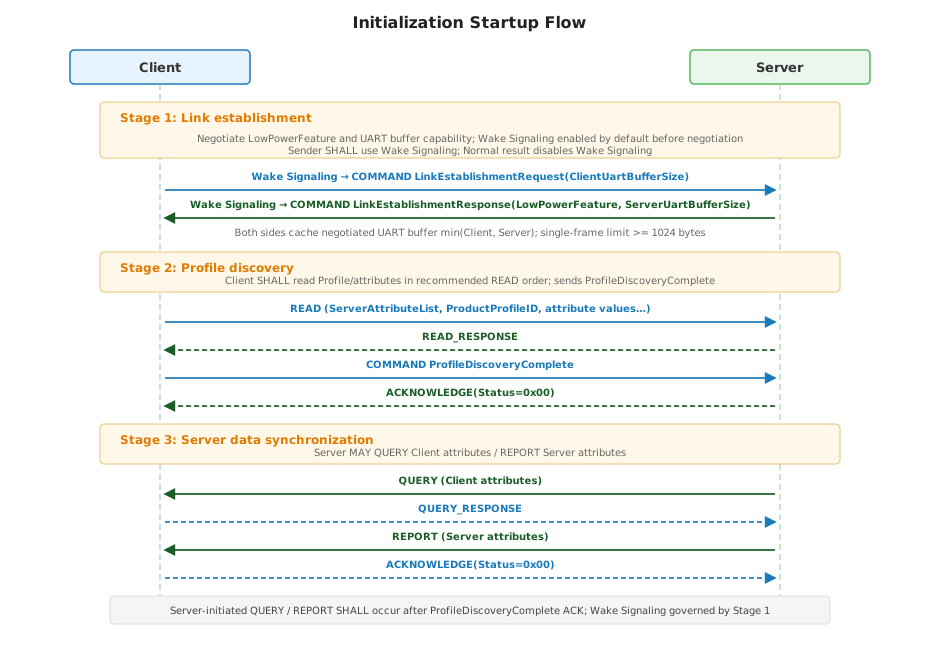
After power-on, Client SHALL execute initialization in the following three stages in order:
- Link establishment: Client sends
LinkEstablishmentRequest(ClientUartBufferSize); Server returnsLinkEstablishmentResponse(LowPowerFeature, ServerUartBufferSize)to negotiate whether Wake Signaling is enabled and to exchange UART buffer capability; both sides use the smaller declared value as the AECP single-frame upper limit (>= 1024 bytes). Before negotiation completes, Wake Signaling is enabled by default; after negotiation, it is disabled only when Server returnsNormal. - Profile discovery: Client READs Server Profiles and attribute initial values, then sends
ProfileDiscoveryComplete; Profile discovery completes after Server ACK. - Server data synchronization: Server QUERYs Client attributes or REPORTs Server attributes as needed; initialization completes afterward and Normal Operation begins.
Before both sides complete LowPowerFeature negotiation, Wake Signaling is enabled by default; during negotiation, the sender SHALL perform Wake Signaling.
Core Concepts
Link Establishment
Link Establishment is the first AECP interaction process after power-on and is used to negotiate whether Wake Signaling is enabled (LowPowerFeature) and to exchange UART buffer capability (ClientUartBufferSize, ServerUartBufferSize). Before negotiation completes, Wake Signaling is enabled by default.
Completion criterion: Client receives LinkEstablishmentResponse and caches LowPowerFeature, ServerUartBufferSize, and the negotiated UART buffer size; Server caches ClientUartBufferSize and the negotiated UART buffer size.
Interaction:
- Client SHALL send
LinkEstablishmentRequest(ClientUartBufferSize)as the first AECP frame after power-on; see ClientUartBufferSizeAttr forClientUartBufferSizesemantics; the value SHALL NOT be less than 1024 bytes; SHALL perform Wake Signaling before sending (enabled by default before negotiation). - Server SHALL return
LinkEstablishmentResponse(LowPowerFeature, ServerUartBufferSize); see ServerUartBufferSizeAttr forServerUartBufferSizesemantics; the value SHALL NOT be less than 1024 bytes; SHALL perform Wake Signaling before sending.
After link establishment completes, both sides SHALL compute and cache the negotiated UART buffer size:
.... Negotiated UART buffer size = min(ClientUartBufferSize, ServerUartBufferSize) ....
The negotiated result SHALL NOT be less than 1024 bytes. For subsequent AECP frames in either direction, the complete frame length (see Interaction Model) SHALL NOT exceed the negotiated UART buffer size.
Before Link Establishment negotiation completes: Wake Signaling is enabled by default; during negotiation, the sender SHALL perform Wake Signaling.
Profile Discovery
Profile Discovery is the process in which Client reads the Server capability view, including Profile discovery, attribute list reading, and attribute initial value reading.
Completion criterion: Client sends ProfileDiscoveryComplete and Server returns ACKNOWLEDGE(Status=0x00).
Client SHALL complete Server product Profile discovery, attribute list reading, and attribute initial value reading before sending ProfileDiscoveryComplete. Server SHALL support Foundation Profile (0x0000) by default and SHALL declare only one product Profile.
Recommended READ order:
- Use
Profile ID = 0x0000to READServerAttributeList(Attribute ID0xFFFB). - Use
Profile ID = 0x0000to READProductProfileID(Attribute ID0x1007). - Use
Profile ID = ProductProfileIDto READ the product Profile'sServerAttributeList(Attribute ID0xFFFB). - Use
Profile ID = 0x0000to READ Foundation Profile Server attributes that require initialization. - Use
Profile ID = ProductProfileIDto READ product Profile Server attributes that require initialization.
Client SHALL use Profile ID = 0x0000 to read the following Foundation Server attributes:
| Attribute ID | Name | Description |
|---|---|---|
0xFFFB | ServerAttributeList | List of Attribute IDs actually supported by Server under Foundation Profile. |
0x1007 | ProductProfileID | Unique product Profile of Server. |
Client SHALL NOT access attributes not declared in ServerAttributeList during product Profile initialization reads.
When LowPowerFeature=LowPower, Client SHALL perform Wake Signaling before each Client→Server READ.
LowPowerFeature
LowPowerFeature is a parameter carried by LinkEstablishmentResponse, with type LowPowerFeatureEnum8 (see LowPowerFeatureEnum8), used to negotiate whether Wake Signaling is enabled. Before both sides complete negotiation, Wake Signaling is enabled by default; Server returning Normal means negotiation disables Wake Signaling.
| Value | Name | Description |
|---|---|---|
0x00 | Normal | Negotiation disables Wake Signaling; after link establishment completes, both sides communicate directly over UART. |
0x01 | LowPower | Default (before negotiation). Keeps Wake Signaling enabled; after link establishment completes, the sender SHALL perform Wake Signaling before each UART communication. |
The LowPowerFeature reported by Server SHALL match the actual low-power capability of the product. Products without low-power sleep and Wake Pin mechanism SHALL return Normal. If such products tie Wake Pin high per Hardware Interface, Chapter 2, the Wake Signaling requirement during link establishment negotiation SHALL be considered satisfied (no actual signaling).
Wake Signaling
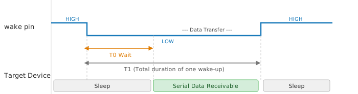
Wake Signaling is the complete process in which the sender, before UART communication, uses the peer's Wake Pin (see Hardware Interface, Chapter 2) to perform active-low assertion → T0 wait → UART transfer → pin release.
This protocol uses an active-low Wake Pin signal. When no data is being transferred, Wake Pin SHALL remain high.
Enable rules:
- Default before negotiation: Before both sides complete
LowPowerFeaturenegotiation, Wake Signaling is enabled by default. - During link establishment negotiation: Because Wake Signaling is enabled by default before negotiation, the sender SHALL perform Wake Signaling.
- Negotiation result
Normal: Wake Signaling disabled; both sides use UART directly. - Negotiation result
LowPower(default): Wake Signaling remains enabled; the sender SHALL perform Wake Signaling before each UART communication (Client→Server and Server→Client).
| Parameter | Name | Description |
|---|---|---|
| T0 | Wait time | After Wake Pin is pulled low, the sender waits for the receiver to complete UART receive preparation. Serial data transmission starts after T0 elapses. |
| T1 | Total signaling duration | Complete duration from Wake Pin pulled low to pulled high again, that is, T0 plus all data transmission time. |
Client → Server
When Client needs to send data to Server, Client pulls Server's Wake Pin low:
- Recommended T0: 5 ms.
- T1: No fixed requirement; determined by actual data transmission duration.
Server → Client
When Server needs to send data to Client, Server pulls Client's Wake Pin low:
- Fixed T0: 20 ms (fixed in the current version; dynamic configuration by command is not supported).
- Client SHALL complete serial receive preparation within T0.
Timeout Handling
When the sender waits for a peer response, the timeout SHALL be set to 100 ms. Retransmission behavior after timeout is defined in Retry Mechanism.
Implementation Notes
- Wake Pin drive capability SHALL meet the input threshold requirements of the target device.
- After data transmission completes, Wake Pin SHOULD be released (pulled high) promptly to avoid preventing the peer from returning to low-power state.
- If low-power functionality is not required, Wake Pin MAY be tied high permanently and Wake Signaling omitted.
Power-on Initialization Flow
Flow Overview
After power-on, Client and Server execute the following three stages in order:
| Stage | Name | Description |
|---|---|---|
| Stage 1 | Link establishment | Negotiate LowPowerFeature and exchange UART buffer capability; use the smaller declared value as the single-frame upper limit (>= 1024 bytes); Wake Signaling enabled by default before negotiation; sender SHALL use Wake Signaling during negotiation; disabled when result is Normal |
| Stage 2 | Profile discovery | Client READ Profile/attributes; ProfileDiscoveryComplete and Server ACK |
| Stage 3 | Server data synchronization | Server QUERY Client attributes or REPORT Server attributes as needed; initialization completes |
Link establishment
After power-on, Client SHALL first perform link establishment (see Link Establishment):
- Client SHALL perform Wake Signaling before sending
LinkEstablishmentRequest(ClientUartBufferSize)(enabled by default before negotiation). - Server SHALL perform Wake Signaling before returning
LinkEstablishmentResponse(LowPowerFeature, ServerUartBufferSize). - Client caches
LowPowerFeature,ServerUartBufferSize, and the negotiated UART buffer size; Server cachesClientUartBufferSizeand the negotiated UART buffer size; link establishment negotiation completes. Wake Signaling is enabled by default before negotiation; disabled only when negotiation result isNormal.
Profile discovery
After link establishment completes, Client SHALL perform Profile discovery (see Profile Discovery), read the Server capability view and attribute initial values in the recommended READ order, then send ProfileDiscoveryComplete.
When triggered by ProfileDiscoveryRequest, Client SHALL redo Profile discovery only (SHALL NOT redo link establishment).
Client SHALL send ProfileDiscoveryComplete with Profile ID = 0x0000. After Server returns ACKNOWLEDGE(Status=0x00), Profile discovery completes. Before Server receives ProfileDiscoveryComplete and ACKs it, it SHALL NOT proactively initiate QUERY, REPORT, or Server → Client COMMAND used to synchronize service data.
Server data synchronization
After Profile discovery completes, Server MAY QUERY Client attributes it needs (Side = C) and MAY REPORT Server attributes (Side = S). Client SHALL return current values by QUERY_RESPONSE upon QUERY; Client SHALL confirm by ACKNOWLEDGE upon REPORT:
| Attribute ID | Name | Description |
|---|---|---|
| 0x0000 | ProtocolVersion | Server retrieves AECP version supported by Client |
| 0x0001 | ModuleFirmwareVersion | Server retrieves Client firmware version |
| 0x0002 | ModuleUniqueID | Server retrieves unique device identifier |
| 0x0003 | PairingStatus | Server retrieves current pairing state |
| 0x0004 | NetworkStatus | Server retrieves current network connection state |
| 0x0005 | LocalTime | Server retrieves current local time |
| 0x0006 | ModuleSupportedProductProfileList | Server retrieves product Profile ID list supported by Client |
| 0x0007 | ClientUartBufferSize | Server retrieves Client UART buffer size |
If Client has not completed Profile discovery, Client MAY return ProfileDiscoveryInProgress for prematurely arriving QUERY, REPORT, or Server → Client data synchronization COMMAND messages.
After Server data synchronization completes, Client and Server enter Normal Operation; whether subsequent UART communication uses Wake Signaling remains governed by LowPowerFeature determined in Stage 1.
Complete Startup Sequence Diagram
Chapter 5 Profile Model and Implementation Rules
This chapter defines the AECP Profile model, as well as the Response Mechanism, retry mechanism, Attributes ID namespace, and Commands ID namespace rules that both communicating sides shall follow during implementation.
A Profile is an application-layer organizational unit of the protocol. Each Profile consists of a group of related Attributes (Attribute) and Commands (Command), and is uniquely identified by Profile ID (uint16).
The Profile ID in the frame header declares the functional domain to which the frame operation belongs. The Server SHALL support the Foundation Profile (0x0000) by default and SHALL declare only one product Profile. After Profile Discovery completes (ProfileDiscoveryComplete ACK), the Client may switch communication between the Foundation Profile and that product Profile.
Profile ID Namespace
The Data Type of Profile ID is uint16, and its value range SHALL follow the table below. Profile IDs not defined in this specification SHALL NOT be used for standard product interoperability.
| Profile ID Scope | Description |
|---|---|
0x0000 | Foundation Profile. All devices SHALL support it. |
0x0001 ~ 0x0FFF | Prohibited. This range SHALL be Reserved and SHALL NOT be allocated to product Profiles. |
0x1000 ~ 0x2000 | Empowerment service Profiles, allocated and defined by this specification. |
0x2001 ~ 0xFFFF | Reserved for future protocol extensions. The current version SHALL NOT allocate or use this range. |
Defined Profile IDs
| Profile ID | Name | Description |
|---|---|---|
0x0000 | Foundation Profile | All devices SHALL support it. Attributes: 0x0000~0x0FFF (Client Attributes), 0x1000~0x1FFF (Server Attributes); Commands are uniformly defined by the Foundation Profile Commands table. |
0x1000 | Thermostat Profile | Attributes and Commands specific to thermostat devices. Server Attributes SHALL use the 0x1000 ~ 0x1FFF segment. If a Server declares the Thermostat Profile, its ProductProfileID is 0x1000. |
Attributes and Commands Addressing Rules
- Attribute ID is unique within its owning Profile. The same Attribute ID value in different Profiles may have different semantics. Full address = Profile ID + Attribute ID. The receiver must combine it with the Profile ID in the frame header to interpret Attributes semantics.
- Command ID is also unique within its Profile. The Profile ID in the frame header and the Command ID together determine Commands semantics.
Attribute Side and Conformance
Each Attribute SHALL mark its Side in the Attributes table through the Side column, and mark its implementation requirement through the Conformance column. Column meanings follow Chapter 1 Field Notation Convention.
| Mark | Owner | Description |
|---|---|---|
| C | Client | The Attribute is owned and maintained by the Client. Typical values include Client self information, such as firmware version and Unique ID, or network capabilities, such as pairing state, network status, and time. When the Server needs to read it, the Server initiates QUERY and the Client returns QUERY_RESPONSE. The Client may also proactively initiate NOTIFY for Attributes whose Access includes NF, and the Server returns ACKNOWLEDGE. |
| S | Server | The Attribute is owned and maintained by the Server. Typical values include sensor data, setting values, and device hardware status. The Client accesses it through READ/WRITE, and the Server proactively reports it through REPORT. |
The Conformance column describes implementation requirements: M (Mandatory, SHALL be implemented); O (Optional, MAY be implemented).
Response Mechanism
Each Operation Code has a defined Response requirement. Except for COMMAND messages whose Commands table explicitly declares Response = N, the receiver SHALL respond to every received message within the timeout:
| Sent by Initiator | Receiver Response | Description |
|---|---|---|
| READ(0x1) | READ_RESPONSE(0x2) | The Server responds with Attributes value and Status. |
| WRITE(0x3) | WRITE_RESPONSE(0x4) | The Server responds with Status. |
| REPORT(0x5) | ACKNOWLEDGE(0x6) | The Client confirms receipt and carries Status. |
| QUERY(0x7) | QUERY_RESPONSE(0x8) | The Client responds with Client Attributes value and Status. |
| NOTIFY(0xA) | ACKNOWLEDGE(0x6) | The Server confirms receipt and carries Status. |
| COMMAND(0x9) | ACKNOWLEDGE(0x6) | When the receiver only needs to confirm the execution result, it returns ACKNOWLEDGE with Status. |
| COMMAND(0x9) | Paired COMMAND(0x9) | When the receiver needs to return data, it returns a paired COMMAND. Whether the paired COMMAND continues to require a Response is determined by its own Response declaration. |
| COMMAND(0x9) | No Response | Used only when this command declares Response = N in the Commands table. |
When waiting for a response, the sender SHALL set the timeout to 100 ms.
Initialization Rules
Power-on initialization SHALL be Client-led and executed in the order Link Establishment → Profile Discovery → Server data sync (see Chapter 4 for details).
Link Establishment
- Client SHALL send
LinkEstablishmentRequest(ClientUartBufferSize)as the first AECP interaction after power-on to negotiateLowPowerFeatureand declare Client UART buffer capability; SHALL perform Wake Signaling before sending (enabled by default before negotiation). - Server SHALL return
LinkEstablishmentResponse(LowPowerFeature, ServerUartBufferSize); SHALL perform Wake Signaling before sending. - After link establishment completes, both sides SHALL compute the negotiated UART buffer size
min(ClientUartBufferSize, ServerUartBufferSize)and use it to constrain subsequent single-frame lengths; each declared value SHALL NOT be less than 1024 bytes. - Before both sides complete
LowPowerFeaturenegotiation, Wake Signaling is enabled by default; during negotiation, the sender SHALL perform Wake Signaling.
Profile Discovery
- Client SHALL READ Server Profiles and attribute initial values after Link Establishment completes.
- When
LowPowerFeature=LowPower, Client SHALL perform Wake Signaling before each Client→Server READ. - After Profile Discovery completes, Client SHALL send
ProfileDiscoveryComplete.
Server Data Sync
- After Profile Discovery completes, Server MAY QUERY Client attributes and MAY REPORT Server attributes.
- Client SHALL return QUERY_RESPONSE to QUERY and ACKNOWLEDGE to REPORT.
Server Synchronization Constraints
Before Server receives ProfileDiscoveryComplete and returns ACKNOWLEDGE(Status=0x00), it SHALL NOT proactively QUERY Client attributes, REPORT Server attributes, or send Server → Client COMMAND used to synchronize service data. If Client has not completed Profile Discovery, Client MAY return ProfileDiscoveryInProgress for early Server-initiated synchronization requests. After ACK completes, Server MAY QUERY or REPORT as needed.
When triggered by ProfileDiscoveryRequest, Client SHALL redo Profile Discovery only (SHALL NOT redo Link Establishment).
Subsequent Client READ, WRITE, or COMMAND operations SHALL be based on the product Profile definition corresponding to ProductProfileID. If the Client accesses an Attribute or Command not defined by that Profile, the Server SHOULD return a non-zero Status.
Retry Mechanism
When the sender times out without receiving a Response, it SHALL start the retry mechanism:
- Each message may be retransmitted up to 3 times (4 attempts in total including the initial transmission).
- Retransmission SHALL use the same sequence number (
Seq) as the original message so that the receiver can identify and deduplicate retransmitted packets. - After all three retransmissions time out, the sender MAY record an error and notify the upper-layer application. The specific handling policy is determined by the product implementation.
Attributes ID Namespace
The Data Type of Attribute ID is uint16, with value range 0x0000 ~ 0xFFFF, and it is unique within its owning Profile. The same Attribute ID value in different Profiles may have different semantics. Full address = Profile ID (frame header) + Attribute ID.
Attribute IDs for all Profiles SHALL follow the segments in the table below. Undefined Attribute IDs SHALL be treated as Reserved. When the receiver receives a request to access an undefined Attribute ID, it SHOULD return UnsupportedAttribute.
| Attribute ID Scope | Description |
|---|---|
0x0000 ~ 0x0FFF | Client Attributes. Owned by the Client. The Server pulls them through QUERY, and the Client returns them through QUERY_RESPONSE. The Client may also proactively NOTIFY Attributes whose Access includes NF. |
0x1000 ~ 0x1FFF | Server Attributes. Owned by the Server. The Client may READ/WRITE them, and the Server may REPORT them. Server local state, capabilities, and control Attributes for each product Profile SHALL be defined in this range. |
0x2000 ~ 0xFFFA | Reserved for future protocol extensions. |
0xFFFB ~ 0xFFFF | Global Attributes range. The current specification defines 0xFFFB ServerAttributeList; each Profile SHALL define this Attribute. Other IDs are Reserved for future global Attributes. |
Commands ID Namespace
The Data Type of Command ID is uint16, with value range 0x0001 ~ 0xFFFF, and it is unique within its owning Profile. Complete Commands identifier = Profile ID (frame header) + Command ID. 0x0000 SHALL be Reserved and SHALL NOT be used as a valid Command ID.
Command IDs for all Profiles SHALL follow the segments in the table below. Undefined Command IDs SHALL be treated as Reserved. When the receiver receives an undefined Command ID, it SHOULD return UnsupportedCommand.
| Command ID Scope | Description |
|---|---|
0x0001 ~ 0x7FFF | Standard Commands, defined by the owning Profile. |
0x8000 ~ 0xFFFF | Reserved for future protocol extensions. The current version SHALL NOT allocate or use this range. |
Each Command SHALL declare Direction in the Commands table of its owning Profile:
Client -> Server: Only the Client is allowed to send this COMMAND as the Initiator, and the Server processes it as the receiver.Server -> Client: Only the Server is allowed to send this COMMAND as the Initiator, and the Client processes it as the receiver.
Each Command SHALL declare Response in the Commands table of its owning Profile:
ACKNOWLEDGE: This command has no paired response Command. The receiver SHALL directly return ACKNOWLEDGE.<CommandName>: This command has a paired response Command. The receiver SHALL return the COMMAND with the specified name.N: This command does not require any Response.NSHOULD be used only for paired return Commands to avoid unbounded Response chains.
When the receiver receives a COMMAND whose Direction does not match, it SHOULD return ACKNOWLEDGE, and Status SHOULD be a non-zero error code.
Profile Definitions
Attributes, Commands, enumerations, bitmaps, and parameter tables for specific Profiles SHALL be maintained in independent Profile definition files:
Chapter 6 Foundation Profile (Profile ID = 0x0000)
Foundation Profile is the base functional profile that all device types must implement. It contains base attributes, base commands, and firmware upgrade capabilities. The Profile ID of all Foundation Profile frames SHALL be 0x0000.
Table Conventions
The column meanings of all attribute, command, and parameter tables in this chapter follow Chapter 1 Field Notation Convention.
Data Types
PairingStatusEnum8
PairingStatusEnum8 defines the Client pairing window and network admission state. The underlying type of this enum is enum8.
| Value | Name | Description |
|---|---|---|
| 0x00 | NotPairing | Client is not in pairing mode and the pairing window is closed; used when not joined to a network or after exiting the pairing flow. |
| 0x01 | Pairing | Client has opened the pairing window and is waiting for or processing network join, authentication, and binding. |
| 0x02 | Paired | Client has completed network join or binding and confirmed that the current network identity is valid. |
NetworkStatusEnum8
NetworkStatusEnum8 defines the Client network connection state. The underlying type of this enum is enum8.
| Value | Name | Description |
|---|---|---|
| 0x00 | Offline | Client is not connected to an available network and cannot perform uplink or downlink services that require network connectivity. |
| 0x01 | Online | Client is connected to an available network and can perform normal network communication and service synchronization. |
| 0x02 | Connecting | Client is trying to join the network, restore connectivity, or perform network authentication; network capability is not yet available. |
OtaUpgradeMethodEnum8
OtaUpgradeMethodEnum8 defines the firmware upgrade methods supported by Server. The underlying type of this enum is enum8.
| Value | Name | Description |
|---|---|---|
| 0x00 | NotSupported | Server does not support OTA. |
| 0x01 | IapOta | Server supports IAP OTA. |
| 0x02 | BootLoaderOta | Server supports BootLoader OTA. |
HardwareFaultMap32
HardwareFaultMap32 defines Server hardware fault bits. The underlying type of this map is map32. A corresponding bit set to 1 indicates that the fault is active.
| Bit | Name | Description |
|---|---|---|
| 0 | GeneralFault | General hardware fault. |
| 1 | RadioFault | Wireless or communication subsystem fault. |
| 2 | SensorFault | Sensor subsystem fault. |
| 3 | RecoverableOverTemperature | Recoverable over-temperature. |
| 4 | NonRecoverableOverTemperature | Non-recoverable over-temperature. |
| 5 | PowerSourceFault | Power source fault. |
| 6 | DisplayFault | Display subsystem fault. |
| 7 | AudioFault | Audio subsystem fault. |
| 8 | UserInterfaceFault | User interface fault. |
| 9 | NonVolatileMemoryFault | Non-volatile memory fault. |
| 10 | PhysicalTamperDetected | Physical tamper detected. |
OtaStatusEnum8
OtaStatusEnum8 defines Server OTA progress state. The underlying type of this enum is enum8.
| Value | Name | Description |
|---|---|---|
| 0x00 | Idle | No OTA is in progress. |
| 0x01 | InProgress | OTA is in progress. |
| 0x02 | VerifyFailed | Firmware verification failed. |
| 0x03 | Complete | OTA image has been verified and applied. |
OtaAbortReasonEnum8
OtaAbortReasonEnum8 defines the reason why Server actively aborts OTA. The underlying type of this enum is enum8.
| Value | Name | Description |
|---|---|---|
| 0x00 | Unspecified | Unspecified reason. |
| 0x01 | ClientCancelled | Client requested OTA cancellation. |
| 0x02 | Timeout | OTA process timed out. |
| 0x03 | InsufficientSpace | Server has insufficient storage space. |
| 0x04 | WriteFailed | Firmware write failed. |
| 0x05 | VerifyFailed | Firmware verification failed. |
| 0x06 | UnsupportedImage | Firmware image type, version, or hardware condition does not match. |
| 0x07 | InvalidState | The current Server state does not allow OTA to continue. |
LowPowerFeatureEnum8
LowPowerFeatureEnum8 defines the low-power feature of Server. The underlying type of this enum is enum8. Client obtains this value through LinkEstablishmentResponse (see Chapter 4) to negotiate whether Wake Signaling is enabled. Before both sides complete negotiation, Wake Signaling is enabled by default.
| Value | Name | Description |
|---|---|---|
| 0x00 | Normal | Negotiation disables Wake Signaling; after link establishment completes, both sides communicate directly over UART. |
| 0x01 | LowPower | Default (before negotiation). Keeps Wake Signaling enabled; after link establishment completes, both sides SHALL perform Wake Signaling before UART communication. |
Client Attributes
| ID | Name | Type | Constraint | Default | Access | Side | Conformance | Description |
|---|---|---|---|---|---|---|---|---|
| 0x0000 | ProtocolVersion | uint16 | Starts from 0 | 0x0000 | Q | C | M | AECP version number. |
| 0x0001 | ModuleFirmwareVersion | uint32 | No additional constraints | - | Q | C | M | Client firmware version. |
| 0x0002 | ModuleUniqueID | octstr | Maximum 255 | - | Q | C | M | unique identifier of Client. |
| 0x0003 | PairingStatus | PairingStatusEnum8 | See enum | - | Q/NF | C | M | pairing state. |
| 0x0004 | NetworkStatus | NetworkStatusEnum8 | See enum | - | Q/NF | C | M | Client network status. |
| 0x0005 | LocalTime | uint32 | No additional constraints | - | Q/NF | C | O | Client local time. |
| 0x0006 | ModuleSupportedProductProfileList | list[uint16] | Non-reserved Profile ID | - | Q | C | M | product Profile list supported by Client. |
| 0x0007 | ClientUartBufferSize | uint16 | >= 1024 bytes | 1024 | Q | C | M | Client UART buffer size. |
ProtocolVersion
ProtocolVersion is maintained by Client and declares the AECP version supported by Client. The version number SHALL increment from 0; the default value of the current version is 0x0000.
When Server needs to determine Client protocol compatibility, it SHALL retrieve this attribute by QUERY, and Client SHALL return the current value by QUERY_RESPONSE.
ModuleFirmwareVersion
ModuleFirmwareVersion is maintained by Client. When Server needs to obtain the Client firmware version, it MAY retrieve this attribute by QUERY, and Client SHALL return the current value by QUERY_RESPONSE.
ModuleUniqueID
ModuleUniqueID is maintained by Client. When Server needs to obtain the unique identifier of Client, it MAY retrieve this attribute by QUERY, and Client SHALL return the current value by QUERY_RESPONSE.
PairingStatus
PairingStatus is maintained by Client. When Server needs to obtain the current pairing state, it SHALL retrieve this attribute by QUERY, and Client SHALL return the current value by QUERY_RESPONSE.
When the pairing state changes, Client SHOULD proactively synchronize the latest value of this attribute to Server by NOTIFY.
Valid values are defined in PairingStatusEnum8.
NetworkStatus
NetworkStatus is maintained by Client. When Server needs to obtain the current network state, it MAY retrieve this attribute by QUERY, and Client SHALL return the current value by QUERY_RESPONSE.
When the network state changes, such as becoming online or offline, Client SHOULD proactively synchronize the latest value of this attribute to Server by NOTIFY.
Valid values are defined in NetworkStatusEnum8.
LocalTime
LocalTime is maintained by Client. The value is Unix Epoch time in seconds, counted from 1970-01-01 00:00:00 UTC.
When Server needs a network synchronization timestamp, it MAY retrieve this attribute by QUERY. Client SHALL return the latest available local time in QUERY_RESPONSE.
ModuleSupportedProductProfileList
ModuleSupportedProductProfileList is maintained by Client and declares the list of product Profile IDs that Client supports for parsing and interaction.
The attribute type is list[uint16]. List elements SHALL be sorted by Profile ID in ascending order. Foundation Profile (0x0000) is mandatory for all Client implementations, is not declared through this attribute, and SHALL NOT appear in this list.
ClientUartBufferSize
ClientUartBufferSize is maintained by Client and declares the Client UART receive and transmit buffer size, in bytes.
The attribute type is uint16, and the default value is 1024. The Client UART receive buffer and transmit buffer SHALL both be no smaller than this value. If the receive and transmit buffer sizes differ, this attribute SHALL use the smaller value as the available single-frame length capability. During link establishment, Client SHALL carry a ClientUartBufferSize parameter in LinkEstablishmentRequest that is consistent with this attribute.
Server Attributes
| ID | Name | Type | Constraint | Default | Access | Side | Conformance | Description |
|---|---|---|---|---|---|---|---|---|
| 0x1000 | VendorID | uint16 | 1 ~ 0xFFFF | 0x0000 | R/RP | S | M | vendor ID. |
| 0x1001 | ProductID | uint16 | 1 ~ 0xFFFF | 0x0000 | R/RP | S | M | product ID. |
| 0x1002 | ServerHardwareVersion | uint16 | 1 ~ 0xFFFF | 0x0001 | R/RP | S | M | Server hardware version. |
| 0x1003 | ServerSoftwareVersion | uint16 | 1 ~ 0xFFFF | 0x0001 | R/RP | S | M | Server firmware version. |
| 0x1004 | OtaUpgradeMethod | OtaUpgradeMethodEnum8 | See enum | 0x00 | R/RP | S | M | OTA Upgrade Method. |
| 0x1005 | OtaStatus | OtaStatusEnum8 | See enum | 0x00 | RP | S | O | OTA status. |
| 0x1006 | HardwareFault | HardwareFaultMap32 | See map | - | R/RP | S | O | hardware fault bitmap. |
| 0x1007 | ProductProfileID | uint16 | Non-reserved Profile ID | - | R/RP | S | M | unique product Profile of Server. |
| 0x1008 | ServerUartBufferSize | uint16 | >= 1024 bytes | 1024 | R/RP | S | M | Server UART buffer size. |
| 0xFFFB | ServerAttributeList | list[uint16] | No additional constraints | - | R/RP | S | M | list of attributes supported by Server. |
VendorID
VendorID identifies the device manufacturer ID. Server SHALL support Client READ access to this attribute.
ProductID
ProductID identifies the device product ID. Server SHALL support Client READ access to this attribute.
ServerHardwareVersion
ServerHardwareVersion identifies the Server hardware version. Server SHALL support Client READ access to this attribute.
ServerSoftwareVersion
ServerSoftwareVersion identifies the Server firmware version. Server SHALL support Client READ access to this attribute.
After OTA completes and the new firmware starts successfully, Server SHALL report the latest value of this attribute by REPORT.
OtaUpgradeMethod
OtaUpgradeMethod declares the firmware upgrade method supported by Server.Valid values are defined in OtaUpgradeMethodEnum8.
Before initiating any OTA flow, Client SHALL first READ this attribute and select IAP OTA, BootLoader OTA, or abandon OTA according to the upgrade method returned by Server.
HardwareFault
HardwareFault is maintained by Server. Client MAY READ this attribute. When any fault bit changes, Server SHOULD REPORT this attribute.
Bit definitions are provided in HardwareFaultMap32.
ProductProfileID
ProductProfileID declares the unique product Profile supported by Server. Foundation Profile (0x0000) is mandatory by default for all devices and is not declared through this attribute.
Server SHALL declare only one non-reserved product Profile ID. The value range of Profile IDs is provided in Profile ID Namespace. If the device implements Thermostat Profile, the value is 0x1000.
ServerUartBufferSize
ServerUartBufferSize is maintained by Server and declares the Server UART receive and transmit buffer size, in bytes.
The attribute type is uint16, and the default value is 1024. The Server UART receive buffer and transmit buffer SHALL both be no smaller than this value. If the receive and transmit buffer sizes differ, this attribute SHALL use the smaller value as the available single-frame length capability. During link establishment, Server SHALL carry a ServerUartBufferSize parameter in LinkEstablishmentResponse that is consistent with this attribute.
OtaStatus
OtaStatus is maintained by Server. When OTA status changes, Server SHOULD REPORT this attribute.
Valid values are defined in OtaStatusEnum8.
ServerAttributeList
ServerAttributeList declares the list of Attribute IDs actually supported by Server under Foundation Profile.
The attribute type is list[uint16].List elements SHALL be sorted by Attribute ID in ascending order, and include ServerAttributeList 's own Attribute ID 0xFFFB.
Foundation Commands
The following commands belong to Foundation Profile and apply to all device types. Firmware-upgrade-related commands are also part of Foundation Profile capabilities and are defined in the same command table.
| ID | Name | Direction | Response | Conformance | Description |
|---|---|---|---|---|---|
| 0x0001 | ProfileDiscoveryComplete | Client → Server | ACKNOWLEDGE | M | Notifies Server that Profile Discovery has completed. |
| 0x0002 | NetworkResetNotify | Client → Server | ACKNOWLEDGE | M | Client notifies Server that the wireless side received a network reset request. |
| 0x0003 | FactoryResetNotify | Client → Server | ACKNOWLEDGE | M | Client notifies Server that the wireless side received a factory reset request. |
| 0x0004 | NetworkResetRequest | Server → Client | ACKNOWLEDGE | M | Server requests Client to reset the network. |
| 0x0005 | FactoryResetRequest | Server → Client | ACKNOWLEDGE | M | Server requests Client to perform factory reset. |
| 0x0006 | EnterPairingMode | Server → Client | ACKNOWLEDGE | M | Server requests Client to enter pairing mode. |
| 0x0007 | ExitPairingMode | Server → Client | ACKNOWLEDGE | M | Server requests Client to exit pairing mode. |
| 0x0008 | Identify | Client → Server | ACKNOWLEDGE | M | Physical identification indication. |
| 0x0009 | ConnectionControlRequest | Server → Client | ACKNOWLEDGE | O | Server requests Client to enable or disable the wireless connection. |
| 0x000A | ProfileDiscoveryRequest | Server → Client | ACKNOWLEDGE | M | Server requests Client to restart Profile Discovery. |
| 0x000B | LinkEstablishmentRequest | Client → Server | LinkEstablishmentResponse | M | Client initiates link establishment and declares Client UART buffer size. |
| 0x000C | LinkEstablishmentResponse | Server → Client | N | M | Server returns low-power feature and Server UART buffer size. |
| 0x0020 | OtaPrepare | Client → Server | ACKNOWLEDGE | O | Declares that the firmware image is ready. |
| 0x0021 | OtaCancel | Client → Server | ACKNOWLEDGE | O | Cancels the upgrade. |
| 0x0022 | OtaChunkRequest | Server → Client | OtaChunkData | O | Requests a firmware chunk. |
| 0x0023 | OtaChunkData | Client → Server | N | O | Returns a firmware chunk. |
| 0x0024 | OtaApplyRequest | Server → Client | OtaApplyResponse | O | Image verification passed; requests switch confirmation. |
| 0x0025 | OtaApplyResponse | Client → Server | N | O | Confirms that Server may switch the image. |
| 0x0026 | OtaAbortNotify | Server → Client | ACKNOWLEDGE | O | Server actively aborts the upgrade. |
Parameterized commands define parameters in the Parameters table of each command. Data Segment encoding rules are defined in COMMAND (OPC = 0x9).
LinkEstablishmentRequest Command
This command is sent by the Client as the first AECP interaction after power-on to initiate Link Establishment (see Link Establishment). The Client SHALL declare its UART buffer capability during link establishment; both sides SHALL use the smaller declared value as the AECP single-frame upper limit. The Client SHALL perform Wake Signaling before sending (enabled by default before negotiation).
Parameters
| Parameter Order | Name | Type | Constraint | Default |
|---|---|---|---|---|
| 1 | ClientUartBufferSize | uint16 | ≥ 1024 bytes | — |
Field Descriptions
- ClientUartBufferSize: Declares the Client UART receive and transmit buffer capability, in bytes, with the same semantics as the Client attribute of the same name (see ClientUartBufferSize Attribute). The Client UART receive buffer and transmit buffer SHALL both be no smaller than this value. If the two buffer sizes differ, this parameter SHALL use the smaller value.
LinkEstablishmentResponse
This command is sent by the Server in response to LinkEstablishmentRequest to report the Server's low-power feature and UART buffer capability. Both sides SHALL use the smaller declared value as the AECP single-frame upper limit. This command is a paired return command; the Client does not return ACKNOWLEDGE upon receiving it.
Parameters
| Parameter Order | Name | Type | Constraint | Default |
|---|---|---|---|---|
| 1 | LowPowerFeature | LowPowerFeatureEnum81 | See enum | — |
| 2 | ServerUartBufferSize | uint16 | ≥ 1024 bytes | — |
Field Descriptions
-
LowPowerFeature: Indicates the Server's low-power feature and negotiates whether Wake Signaling is enabled. Valid values are defined in LowPowerFeatureEnum8.
Before both sides complete negotiation, Wake Signaling is enabled by default; the Server returningNormalmeans negotiation disables Wake Signaling (see LowPowerFeature). TheLowPowerFeaturereported by Server SHALL match the actual low-power capability of the product. Products without low-power sleep and Wake Pin mechanism SHALL returnNormal. -
ServerUartBufferSize: Indicates the Server's UART receive and transmit buffer capability, in bytes, with the same semantics as the homonymous Server attribute (see ServerUartBufferSize Attribute). The Server UART receive buffer and transmit buffer SHALL both be no smaller than this value. If the two buffer sizes differ, this parameter SHALL use the smaller value.
ProfileDiscoveryComplete
This command is sent by Client after completing Profile Discovery (see Chapter 4). It notifies Server that the Client-side Profile Discovery stage has completed and that Server can start proactive data synchronization.
After Server receives this command and returns ACKNOWLEDGE(Status=0x00), it MAY start QUERY operations to retrieve Client attributes and MAY REPORT Server attributes according to the attribute reporting policy. If Server initiates QUERY, REPORT, or a Server → Client COMMAND used to synchronize service data before receiving this command, Client MAY return ProfileDiscoveryInProgress.
This command has no parameters.
ProfileDiscoveryRequest
This command is sent by Server to request Client to restart Profile Discovery (see Profile Discovery). Typical use cases include Server capability changes or updates to Profile or ServerAttributeList that require Client to re-read Server attributes and refresh its capability view.
After accepting this command, Client SHALL return the execution result by ACKNOWLEDGE and restart Profile Discovery by reading ProductProfileID, the ServerAttributeList of Foundation Profile and the product Profile, and the initial values of Server attributes that require initialization. After Client completes Profile Discovery again, it SHALL send ProfileDiscoveryComplete again.
While Client is performing rediscovery, Client MAY return ProfileDiscoveryInProgress for proactively initiated QUERY, REPORT, or Server → Client COMMAND messages from Server. After Server receives ACKNOWLEDGE for ProfileDiscoveryRequest, it SHALL treat Client as not having completed Profile Discovery, and SHALL NOT proactively QUERY Client attributes or REPORT Server attributes until it receives the new ProfileDiscoveryComplete and returns ACKNOWLEDGE(Status=0x00).
This command has no parameters.
NetworkResetNotify
This command is sent by Client after the wireless side receives a network reset request. It notifies Server to synchronously perform actions such as local network-state cleanup, service-state reset, or user indication.
This command has no parameters.
FactoryResetNotify
This command is sent by Client after the wireless side receives a factory reset request. It notifies Server to erase locally persisted user parameters and runtime parameters and restore factory state.
This command has no parameters.
NetworkResetRequest
This command is sent by Server when a local network reset flow is triggered. It requests Client to clear wireless-network-related state and leave the current network.
This command has no parameters.
FactoryResetRequest
This command is sent by Server when a local factory reset flow is triggered. It requests Client to clear wireless network state, user binding state, and other wireless-side persistent state related to factory restoration.
This command has no parameters.
EnterPairingMode
This command is sent by Server to request Client to open the pairing window and enter pairing mode. After accepting the request, Client SHOULD update PairingStatus and synchronize it by NOTIFY when the state changes.
This command has no parameters.
ExitPairingMode
This command is sent by Server to request Client to close the pairing window and exit pairing mode. After accepting the request, Client SHOULD update PairingStatus and synchronize it by NOTIFY when the state changes.
This command has no parameters.
ConnectionControlRequest
This command is sent by Server to request Client to enable or disable the wireless connection. After accepting the request, Client SHALL return the execution result by ACKNOWLEDGE.
Parameters
| Parameter Order | Name | Type | Constraint | Default |
|---|---|---|---|---|
| 1 | Enabled | bool | 0x00 = false, 0x01 = true | — |
Field Descriptions
Enabled = true: Client SHALL enable RF transceiver functionality and attempt to join the wireless network. While connecting, Client SHOULD updateNetworkStatustoConnecting. After connection succeeds, Client SHOULD update it toOnlineand synchronize it by NOTIFY when the state changes.Enabled = false: Client SHALL disable RF transceiver functionality and disconnect from the wireless network. Client SHOULD updateNetworkStatustoOfflineand synchronize it by NOTIFY when the state changes.
Identify
This command requests Server to perform a physical identification action, such as blinking an LED or sounding a buzzer.
Parameters
| Parameter Order | Name | Type | Constraint | Default |
|---|---|---|---|---|
| 1 | Duration | uint16 | No additional constraints | — |
Field Descriptions
Duration specifies the duration of the identification action, in seconds. A value of 0 means stopping the current identification action.
Firmware Upgrade (OTA)
Foundation Profile defines two firmware upgrade methods:
| Upgrade Method | Use Case |
|---|---|
| IAP OTA | Server receives firmware chunks while the application is running and switches image after verification succeeds. |
| BootLoader OTA | Client notifies Server to enter BootLoader; subsequent firmware transfer is carried by XMODEM. |
OTA Capability Selection Flow
Before initiating any OTA flow, Client SHALL use Profile ID = 0x0000 to READ OtaUpgradeMethod (Attribute ID 0x1004):
| Return Value | Name | Client Behavior |
|---|---|---|
0x00 | NotSupported | Server does not support OTA, and Client SHALL NOT initiate OTA. |
0x01 | IapOta | Client SHALL use the IAP OTA command flow. |
0x02 | BootLoaderOta | Client SHALL use the BootLoader OTA flow and support GPIO entry into BootLoader according to hardware requirements. |
If READ OtaUpgradeMethod fails, Client SHALL NOT initiate OTA. Client must not directly send OtaPrepare or trigger BootLoader entry timing when Server OTA capability is unknown.
OTA Version Compatibility Requirements
To ensure firmware capability compatibility between Client and Server, when Server firmware is upgraded, Client firmware SHALL be upgraded in the same OTA task. Client SHALL NOT start its own OTA before confirming that Server OTA succeeded. If Server OTA success cannot be confirmed, Client SHALL terminate the current OTA.
IAP OTA Flow
IAP OTA uses a Client declares the image, Server actively pulls chunks flow. During the Server OTA stage, Client provides Server firmware data, and Server requests chunks, writes them, verifies them, and finally applies the image. After verification of the complete image succeeds, Server SHALL use OtaApplyRequest to request Client confirmation for switching the image. Server starts switching the image and rebooting only after Client confirms.
Client SHALL use the commands in this section only when OtaUpgradeMethod = IapOta.
OtaPrepare
This command notifies Server that Client is ready to provide the firmware image. Server enters the chunk-pull stage only after ACKNOWLEDGE returns Status = 0x00.
Parameters
| Parameter Order | Name | Type | Constraint | Default |
|---|---|---|---|---|
| 1 | FirmwareSize | uint32 | No additional constraints | — |
| 2 | Crc16 | uint32 | No additional constraints | — |
Field Descriptions
FirmwareSize: firmware body size, in bytes, excluding the OTA Header.Crc16: CRC16/XMODEM checksum value of the firmware body.
OtaCancel
This command cancels the current OTA flow. After accepting this command, Server SHALL reset the OTA state machine.
This command has no parameters.
OtaChunkRequest
This command is sent by Server to request a specified firmware chunk from Client.
Parameters
| Parameter Order | Name | Type | Constraint | Default |
|---|---|---|---|---|
| 1 | Offset | uint32 | No additional constraints | — |
| 2 | Length | uint8 | 1 ~ 255 | — |
Field Descriptions
Offset: requested data offset, in bytes.Length: requested data length, value range1 ~ 255.
OtaChunkData
This command returns the firmware chunk requested by OtaChunkRequest. This command is a paired return command, and Server does not return ACKNOWLEDGE after receiving it.
Parameters
| Parameter Order | Name | Type | Constraint | Default |
|---|---|---|---|---|
| 1 | Offset | uint32 | No additional constraints | — |
| 2 | Data | octstr | Length is chunk size, 1 ~ 255 | — |
Field Descriptions
Offset: firmware data offset, in bytes.Data: firmware data chunk, encoded as octstr. The following byte content has a maximum length of 255.
OtaApplyRequest
This command is sent by Server after firmware image reception completes and verification succeeds. It notifies Client that the image can be applied and requests Client to confirm whether Server is allowed to switch the image. Client SHALL respond with OtaApplyResponse.
This command has no parameters.
OtaApplyResponse
This command indicates that Client has confirmed that Server may switch the image. This command is a paired return command, and Server does not return ACKNOWLEDGE after receiving it. After receiving OtaApplyResponse, Server SHALL start switching the image and reboot.
This command has no parameters.
OtaAbortNotify
This command is sent by Server when OTA encounters an unrecoverable error. Client SHALL ACKNOWLEDGE this command and reset the OTA state machine.
Parameters
[width="100%", cols="^10,^20,^24,^20,^10", options="header"] |=== | Parameter Order | Name | Type | Constraint | Default
| 1 | Reason | OtaAbortReasonEnum8 | See enum | — |
Field Descriptions
Reason: abort reason. Valid values are defined in OtaAbortReasonEnum8.
Normal IAP OTA Flow
The normal IAP OTA flow consists of seven stages:
- Preparation stage: Client sends
OtaPrepareto declare the firmware size and firmware body CRC. Server enters the transfer stage after returningACKNOWLEDGE(Status=0x00). - Transfer stage: Server repeatedly sends
OtaChunkRequestas needed to pull firmware chunks with the specified Offset and Length. Client returns the corresponding data withOtaChunkData. BecauseOtaChunkDatahasResponse = N, Server does not return ACKNOWLEDGE after receiving it. - Verification stage: After receiving the complete image, Server verifies the firmware body CRC. If verification fails, Server reports the failure state by
OtaStatusREPORT or actively aborts by sendingOtaAbortNotify. - Apply confirmation stage: After verification succeeds, Server sends
OtaApplyRequest. After Client returnsOtaApplyResponse, Server SHALL start switching the image and reboot. - Server version confirmation stage: After Server switches to the new image and re-enters the application, it SHALL report the latest value of
ServerSoftwareVersionby REPORT. Client SHALL check whether the version is the target version and returnACKNOWLEDGE(Status=0x00)for confirmation. - Client OTA stage: After Client confirms that Server OTA succeeded, it SHALL perform its own OTA. Server OTA and Client OTA SHALL be upgraded as a pair to ensure firmware version compatibility between both sides.
- Re-initialization stage: After Client OTA completes and Client reboots, Client SHALL perform Link Establishment and Profile Discovery again (see Chapter 4), reading
ProductProfileID, each Profile'sServerAttributeList, and the current values of discovered Server attributes. After Client completes rediscovery, it SHALL sendProfileDiscoveryCompleteagain. Before Server returnsACKNOWLEDGE(Status=0x00), it SHALL NOT proactively QUERY Client attributes or REPORT Server attributes. After ACK completes, Server MAY restart proactive data synchronization to ensure that Server's updated capabilities and Client's updated protocol stack capabilities are synchronized again.
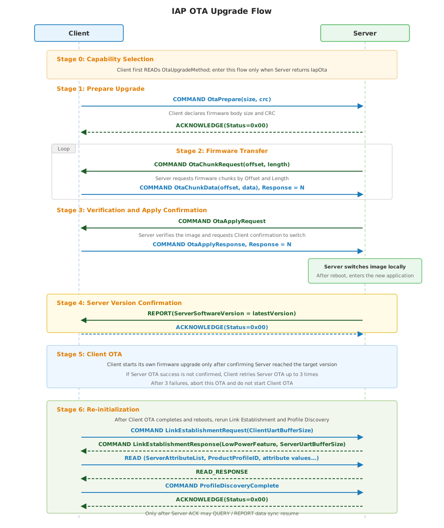
Exceptional IAP OTA Flows
Client cancellation:
Client MAY send OtaCancel to cancel the current OTA. After accepting it, Server SHALL return ACKNOWLEDGE(Status=0x00) and reset the OTA state machine.
Verification failure report:
When verification fails, Server SHALL report the failure state with OtaStatus = VerifyFailed, and Client SHALL confirm the REPORT with ACKNOWLEDGE(Status=0x00).
Server OTA success confirmation failure:
After Client enters the Server OTA flow, it SHALL use the ServerSoftwareVersion REPORT as the basis for determining Server OTA success. If Client does not receive the REPORT within the timeout period, or if the received version is not the target version, Client SHALL retry the Server OTA flow, up to 3 times. If Server OTA success still cannot be confirmed after 3 retries, Client SHALL terminate the current OTA and SHALL NOT start its own OTA.
Server active abort:
Server MAY send OtaAbortNotify(reason) to actively abort the current OTA, and Client SHALL confirm the COMMAND with ACKNOWLEDGE(Status=0x00).
IAP OTA Timeout Mechanism
After Client sends OtaPrepare, it SHALL start the OTA timeout timer and refresh it each time it receives OtaChunkRequest. After Server accepts OtaPrepare, it SHOULD start the OTA timeout timer and refresh it each time it receives OtaChunkData.
OTA Header Parsing
Server SHALL parse the 128-byte OTA Header from the start of the firmware file. If the first OtaChunkData chunk is less than 128 bytes, Server SHALL merge subsequent chunks until the complete OTA Header is obtained.
BootLoader OTA
BootLoader OTA is used to uniformly describe, under AECP, the flow in which Server enters BootLoader and then completes firmware transfer through the standard XMODEM protocol.
Unlike IAP OTA, BootLoader OTA does not transfer firmware chunks through AECP attributes or commands.
Client SHALL use the flow in this section only when OtaUpgradeMethod = BootLoaderOta.
BootLoader OTA Entry Method
BootLoader OTA SHALL enter BootLoader through hardware. Client controls Server entry into BootLoader through a dedicated GPIO, reset pin, or Boot selection pin.
BootLoader OTA Flow
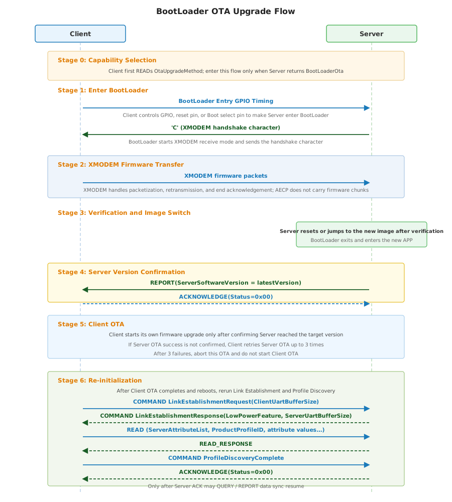
The normal BootLoader OTA flow consists of seven stages:
- Capability selection stage: Before initiating BootLoader OTA, Client SHALL first READ
OtaUpgradeMethodand enter this flow only when Server returnsBootLoaderOta. - BootLoader entry stage: Client controls Server entry into BootLoader through a GPIO, reset pin, or Boot selection pin. After Server enters BootLoader, it starts the XMODEM receive flow and sends the handshake character
'C'. - XMODEM firmware transfer stage: After receiving
'C', Client transfers firmware packets according to the standard XMODEM protocol. AECP does not carry BootLoader OTA firmware chunks, retransmissions, or end acknowledgements. - Verification and image switch stage: After Server receives the complete firmware through XMODEM and completes verification, it resets itself or jumps to the new image.
- Server version confirmation stage: After Server re-enters the application, it SHALL report the latest value of
ServerSoftwareVersionby REPORT. Client SHALL check whether the version is the target version and returnACKNOWLEDGE(Status=0x00)for confirmation. - Client OTA stage: After Client confirms that Server OTA succeeded, it SHALL perform its own OTA. Server OTA and Client OTA SHALL be upgraded as a pair to ensure firmware version compatibility between both sides.
- Re-initialization stage: After Client OTA completes and Client reboots, Client SHALL perform Link Establishment and Profile Discovery again (see Chapter 4), reading
ProductProfileID, each Profile'sServerAttributeList, and the current values of discovered Server attributes. After Client completes rediscovery, it SHALL sendProfileDiscoveryCompleteagain. Before Server returnsACKNOWLEDGE(Status=0x00), it SHALL NOT proactively QUERY Client attributes or REPORT Server attributes. After ACK completes, Server MAY restart proactive data synchronization to ensure that Server's updated capabilities and Client's updated protocol stack capabilities are synchronized again.
After BootLoader OTA enters the Server upgrade process, Client SHALL use the ServerSoftwareVersion REPORT as the basis for determining Server OTA success. If Client does not receive the REPORT within the timeout period, or if the received version is not the target version, Client SHALL retry the Server OTA flow, up to 3 times. If Server OTA success still cannot be confirmed after 3 retries, Client SHALL terminate the current OTA and SHALL NOT start its own OTA.
OTA Header Format
All OTA firmware files SHALL contain a fixed 128-byte OTA Header at the start. The OTA Header is the only structure in AECP that uses Little-Endian encoding. This Little-Endian encoding applies only to Header fields inside the firmware file and does not apply to AECP communication frames, attribute values, or command parameters.
The types in the following table are OTA Header file field types, not AECP Data Types:
Uint32LE: 4-byte unsigned integer, Little-Endian.Utf8String[48]: fixed 48-byte UTF-8 string area, padded with NULL at the end.Reserved[28]: fixed 28-byte reserved area, SHALL be filled with0x00.
| Offset | Field | Type | Size | Description |
|---|---|---|---|---|
| 0 | headerIdentifier | Uint32LE | 4 B | Fixed identifier 0x6C756D69. |
| 4 | headerVersion | Uint32LE | 4 B | Header format version, fixed to 0x00000000. |
| 8 | headerLength | Uint32LE | 4 B | Header Length, fixed to 128. |
| 12 | timestamp | Uint32LE | 4 B | Firmware build timestamp, Unix Epoch seconds. |
| 16 | manufacturerCode | Uint32LE | 4 B | Manufacturer code. |
| 20 | imageType | Uint32LE | 4 B | Image Type: 0 = APP, 1 = BootLoader. |
| 24 | imageTagId | Uint32LE | 4 B | Image Tag ID, Scope 0x0000 ~ 0xFFFF. |
| 28 | imageUpdateAddress | Uint32LE | 4 B | Target Flash address. |
| 32 | imageFileSize | Uint32LE | 4 B | Firmware image size, excluding the OTA Header. |
| 36 | imageFileCrc16 | Uint32LE | 4 B | CRC16/XMODEM checksum value of the firmware image. |
| 40 | imageSoftwareVersion | Uint32LE | 4 B | Image software version. |
| 44 | imageHardwareVersion | Uint32LE | 4 B | Image hardware version. |
| 48 | imageFileName | Utf8String[48] | 48 B | Image file name, UTF-8 string, padded with NULL at the end. |
| 96 | reserved | Reserved[28] | 28 B | Reserved field. SHALL be filled with 0x00. |
| 124 | headerCrc16 | Uint32LE | 4 B | Header CRC16/XMODEM checksum value, covering Offset 0 through 123. |
CRC16/XMODEM Implementation
OTA Header and firmware image verification use CRC16/XMODEM:
- Initial value:
0x0000 - Polynomial:
0x1021
uint16_t imageFileCrc16(uint16_t u16Crc, const uint8_t *buf, uint32_t u32len)
{
    uint16_t crc = u16Crc;
    uint32_t len = u32len;

    while (len--) {
        int i;
        crc ^= (uint16_t)(*buf++) << 8;
        for (i = 0; i < 8; ++i) {
            if (crc & 0x8000)
                crc = (crc << 1) ^ 0x1021;
            else
                crc = crc << 1;
        }
    }
    return crc;
}
The initial value of CRC16/XMODEM is 0x0000, which differs from CRC16-Modbus (Overall Checksum uses 0xFFFF). Do not mix them.
Chapter 7 Thermostat Profile (Profile ID = 0x1000)
Thermostat Profile defines thermostat-specific attributes and commands, and applies to communication frames whose header Profile ID is 0x1000.
All devices that implement Thermostat Profile SHALL also implement Foundation Profile (0x0000) with all attributes and commands defined there.
Table Conventions
The column meanings of all attribute tables in this chapter follow Chapter 1 Field Notation Convention.
Data Types
ThermostatSystemModeEnum8
ThermostatSystemModeEnum8 defines the basic operating mode of a thermostat. The underlying type of this enum is enum8.
| Value | Name | Description |
|---|---|---|
| 0x00 | Off | Off. |
| 0x01 | Auto | Auto mode. |
| 0x02 | Cool | Cooling mode. |
| 0x03 | Heat | Heating mode. |
KeypadLockoutEnum8
KeypadLockoutEnum8 defines the local keypad lockout state. The underlying type of this enum is enum8.
| Value | Name | Description |
|---|---|---|
| 0x00 | Unlocked | Keypad lock is disabled. |
| 0x01 | Locked | Keypad lock enabled. |
TemperatureDisplayModeEnum8
TemperatureDisplayModeEnum8 defines the temperature display unit. The underlying type of this enum is enum8.
| Value | Name | Description |
|---|---|---|
| 0x00 | Celsius | Celsius. |
| 0x01 | Fahrenheit | Fahrenheit. |
Attributes
| ID | Name | Type | Constraint | Default | Access | Side | Conformance | Description |
|---|---|---|---|---|---|---|---|---|
| 0x1000 | SystemMode | ThermostatSystemModeEnum8 | See enum | 0x00 | R/W/RP | S | M | basic operating mode. |
| 0x1001 | OccupiedHeatingSetpoint | int16 | Device capability range | - | R/W/RP | S | M | heating setpoint. |
| 0x1002 | LocalTemperature | int16 | 0.01degC | - | R/RP | S | M | measured ambient temperature. |
| 0x1003 | LocalTemperatureCalibration | int8 | 0.1degC | 0 | R/W/RP | S | M | local temperature calibration. |
| 0x1004 | KeypadLockout | KeypadLockoutEnum8 | See enum | 0x00 | R/W/RP | S | O | keypad lockout state. |
| 0x1005 | TemperatureDisplayMode | TemperatureDisplayModeEnum8 | See enum | 0x00 | R/W/RP | S | O | temperature display unit. |
| 0x1006 | FrostProtectionEnabled | bool | true / false | false | R/W/RP | S | O | frost protection enable switch. |
| 0x1007 | FrostProtectionTemperature | int16 | 0.01degC | - | R/W/RP | S | O | frost protection trigger temperature. |
| 0x1008 | WindowDetectionEnabled | bool | true / false | false | R/W/RP | S | O | open-window detection enable switch. |
| 0x1009 | ActiveCurrent | uint32 | mA | - | RP | S | O | current. |
| 0x100A | ActivePower | uint32 | mW | - | RP | S | O | current power. |
| 0xFFFB | ServerAttributeList | list[uint16] | No additional constraints | - | R/RP | S | M | list of attributes supported by Server. |
SystemMode
SystemMode represents the current basic operating mode of the thermostat. Client MAY WRITE this attribute to switch the operating mode. Server SHALL REPORT this attribute after the mode changes.
Valid values are defined in ThermostatSystemModeEnum8.
OccupiedHeatingSetpoint
OccupiedHeatingSetpoint represents the occupied heating target temperature, in units of 0.01degC. For example, 2650 means 26.50degC, and -900 means -9.00degC.
Client MAY WRITE this attribute to modify the heating target temperature. Server SHALL REPORT this attribute after the target temperature changes.
LocalTemperature
LocalTemperature represents the ambient temperature measured by the Server sensor, in units of 0.01degC. For example, 2650 means 26.50degC.
This attribute is maintained by Server, Client MAY READ, Server SHALL REPORT when temperature changes satisfy the product reporting policy.
LocalTemperatureCalibration
LocalTemperatureCalibration represents the local temperature calibration offset, in units of 0.1degC. For example, 20 means +2.0degC.
Final local temperature = LocalTemperature + LocalTemperatureCalibration. Client MAY WRITE this attribute to adjust the calibration offset.
KeypadLockout
KeypadLockout represents the local keypad lockout state.Client MAY WRITE this attribute to enable or disable keypad lockout.
Valid values are defined in KeypadLockoutEnum8.
TemperatureDisplayMode
TemperatureDisplayMode represents the temperature display unit. Client MAY WRITE this attribute to switch the display unit.
Valid values are defined in TemperatureDisplayModeEnum8.
FrostProtectionEnabled
FrostProtectionEnabled indicates whether frost protection is enabled. true means enabled, false means disabled.
FrostProtectionTemperature
FrostProtectionTemperature represents the frost protection trigger temperature, in units of 0.01degC. When ambient temperature is lower than this value and frost protection is enabled, Server MAY automatically start heating for frost protection.
WindowDetectionEnabled
WindowDetectionEnabled indicates whether open-window detection is enabled. true means enabled, false means disabled.
ActiveCurrent
ActiveCurrent represents the current, in mA. Server SHOULD REPORT this attribute according to the product-defined period or change policy.
ActivePower
ActivePower represents the current power, in mW. Server SHOULD REPORT this attribute according to the product-defined period or change policy.
ServerAttributeList
ServerAttributeList declares the Attribute ID list actually supported by Server under Thermostat Profile.
The attribute type is list[uint16]. List elements SHALL be sorted by Attribute ID in ascending order and include ServerAttributeList's own Attribute ID 0xFFFB.
Appendix A: UART Message Examples
This appendix provides complete UART message examples for typical interaction scenarios, including byte-by-byte annotations, to help implementers verify frame construction and parsing logic.
Example Scenario Description
The following examples are based on the Foundation Profile (Profile ID = 0x0000; Thermostat example uses 0x1000). Frames sent by the Client are marked CLIENT SEND; frames sent by the Server are marked SERVER SEND.
READ and READ_RESPONSE
Attributes Definition
| Attribute ID | Name | Data Type | Side | Access | Description |
|---|---|---|---|---|---|
| 0x1003 | ServerSoftwareVersion | uint16 | S | R/RP | Server firmware version. |
Frame Content
READ Frame (CLIENT SEND)
| Field | SOF | Profile ID | Seq | OPC | D-Len | HCS | Attribute ID |
|---|---|---|---|---|---|---|---|
| Length | 1 B | 2 B | 1 B | 1 B | 2 B | 1 B | 2 B |
| Value (Hex) | 55 | 00 00 | 01 | 01 | 00 02 | A7 | 10 03 |
The last 2 bytes 71 4C are the Overall Checksum.
Complete frame (Hex): 55 00 00 01 01 00 02 A7 10 03 71 4C
READ_RESPONSE Frame (SERVER SEND)
| Field | SOF | Profile ID | Seq | OPC | D-Len | HCS | Attr ID | Status | Data Type | Data |
|---|---|---|---|---|---|---|---|---|---|---|
| Length | 1 B | 2 B | 1 B | 1 B | 2 B | 1 B | 2 B | 1 B | 1 B | 2 B |
| Value (Hex) | 55 | 00 00 | 01 | 02 | 00 06 | A2 | 10 03 | 00 | 21 | 00 63 |
The last 2 bytes A8 56 are the Overall Checksum.
Complete frame (Hex): 55 00 00 01 02 00 06 A2 10 03 00 21 00 63 A8 56
REPORT and ACKNOWLEDGE
Attributes Definition
| Attribute ID | Name | Data Type | Side | Access | Description |
|---|---|---|---|---|---|
| 0x1005 | OtaStatus | enum8 | S | RP | OTA status. |
Frame Content
REPORT Frame (SERVER SEND)
| Field | SOF | Profile ID | Seq | OPC | D-Len | HCS | Attr ID | Data Type | Data |
|---|---|---|---|---|---|---|---|---|---|
| Length | 1 B | 2 B | 1 B | 1 B | 2 B | 1 B | 2 B | 1 B | 1 B |
| Value (Hex) | 55 | 00 00 | 08 | 05 | 00 04 | 9A | 10 05 | 30 | 02 |
The last 2 bytes 24 81 are the Overall Checksum.
Complete frame (Hex): 55 00 00 08 05 00 04 9A 10 05 30 02 24 81
ACKNOWLEDGE Frame (CLIENT SEND)
| Field | SOF | Profile ID | Seq | OPC | D-Len | HCS | Status |
|---|---|---|---|---|---|---|---|
| Length | 1 B | 2 B | 1 B | 1 B | 2 B | 1 B | 1 B |
| Value (Hex) | 55 | 00 00 | 08 | 06 | 00 01 | 9C | 00 |
The last 2 bytes 40 BF are the Overall Checksum.
Complete frame (Hex): 55 00 00 08 06 00 01 9C 00 40 BF
WRITE and WRITE_RESPONSE
Attributes Definition
Profile ID = 0x1000 (Thermostat Profile).
| Attribute ID | Name | Data Type | Side | Access | Description |
|---|---|---|---|---|---|
| 0x1000 | SystemMode | enum8 | C | W | System mode. |
Frame Content
WRITE Frame (CLIENT SEND)
| Field | SOF | Profile ID | Seq | OPC | D-Len | HCS | Attr ID | Data Type | Data |
|---|---|---|---|---|---|---|---|---|---|
| Length | 1 B | 2 B | 1 B | 1 B | 2 B | 1 B | 2 B | 1 B | 1 B |
| Value (Hex) | 55 | 10 00 | 02 | 03 | 00 04 | 92 | 10 00 | 30 | 03 |
The last 2 bytes E5 50 are the Overall Checksum.
Complete frame (Hex): 55 10 00 02 03 00 04 92 10 00 30 03 E5 50
WRITE_RESPONSE Frame (SERVER SEND)
| Field | SOF | Profile ID | Seq | OPC | D-Len | HCS | Attr ID | Status |
|---|---|---|---|---|---|---|---|---|
| Length | 1 B | 2 B | 1 B | 1 B | 2 B | 1 B | 2 B | 1 B |
| Value (Hex) | 55 | 10 00 | 02 | 04 | 00 03 | 92 | 10 00 | 00 |
The last 2 bytes 05 70 are the Overall Checksum.
Complete frame (Hex): 55 10 00 02 04 00 03 92 10 00 00 05 70
QUERY and QUERY_RESPONSE
Attributes Definition
| Attribute ID | Name | Data Type | Side | Access | Description |
|---|---|---|---|---|---|
| 0x0000 | ProductProfileID | uint16 | C | Q | Client product Profile ID. |
Frame Content
QUERY Frame (SERVER SEND)
| Field | SOF | Profile ID | Seq | OPC | D-Len | HCS | Attribute ID |
|---|---|---|---|---|---|---|---|
| Length | 1 B | 2 B | 1 B | 1 B | 2 B | 1 B | 2 B |
| Value (Hex) | 55 | 00 00 | 03 | 07 | 00 02 | 9F | 00 00 |
The last 2 bytes B0 01 are the Overall Checksum.
Complete frame (Hex): 55 00 00 03 07 00 02 9F 00 00 B0 01
QUERY_RESPONSE Frame (CLIENT SEND)
| Field | SOF | Profile ID | Seq | OPC | D-Len | HCS | Attr ID | Status | Data Type | Data |
|---|---|---|---|---|---|---|---|---|---|---|
| Length | 1 B | 2 B | 1 B | 1 B | 2 B | 1 B | 2 B | 1 B | 1 B | 2 B |
| Value (Hex) | 55 | 00 00 | 03 | 08 | 00 06 | 9A | 00 00 | 00 | 21 | 00 00 |
The last 2 bytes 11 50 are the Overall Checksum.
Complete frame (Hex): 55 00 00 03 08 00 06 9A 00 00 00 21 00 00 11 50
COMMAND
InitDiscoveryComplete and ACKNOWLEDGE
COMMAND Frame (CLIENT SEND)
| Field | SOF | Profile ID | Seq | OPC | D-Len | HCS | Cmd ID |
|---|---|---|---|---|---|---|---|
| Length | 1 B | 2 B | 1 B | 1 B | 2 B | 1 B | 2 B |
| Value (Hex) | 55 | 00 00 | 04 | 09 | 00 02 | 9C | 00 01 |
The last 2 bytes 70 C0 are the Overall Checksum.
Complete frame (Hex): 55 00 00 04 09 00 02 9C 00 01 70 C0
ACKNOWLEDGE Frame (SERVER SEND)
| Field | SOF | Profile ID | Seq | OPC | D-Len | HCS | Status |
|---|---|---|---|---|---|---|---|
| Length | 1 B | 2 B | 1 B | 1 B | 2 B | 1 B | 1 B |
| Value (Hex) | 55 | 00 00 | 04 | 06 | 00 01 | A0 | 00 |
The last 2 bytes 40 BF are the Overall Checksum.
Complete frame (Hex): 55 00 00 04 06 00 01 A0 00 40 BF
OtaChunkRequest and OtaChunkData (Paired Response)
Each command parameter is encoded as Data Type (1 B) + Raw Data.
OtaChunkRequest Frame (SERVER SEND)
| Field | SOF | Profile ID | Seq | OPC | D-Len | HCS | Cmd ID | Offset Type | Offset | Length Type | Length |
|---|---|---|---|---|---|---|---|---|---|---|---|
| Length | 1 B | 2 B | 1 B | 1 B | 2 B | 1 B | 2 B | 1 B | 4 B | 1 B | 1 B |
| Value (Hex) | 55 | 00 00 | 06 | 09 | 00 09 | 93 | 00 22 | 23 | 00 00 00 00 | 20 | 04 |
The last 2 bytes F0 83 are the Overall Checksum.
Complete frame (Hex): 55 00 00 06 09 00 09 93 00 22 23 00 00 00 00 20 04 F0 83
OtaChunkData Frame (CLIENT SEND, Response = N)
| Field | SOF | Profile ID | Seq | OPC | D-Len | HCS | Cmd ID | Offset Type | Offset | Data Type | Data (octstr) |
|---|---|---|---|---|---|---|---|---|---|---|---|
| Length | 1 B | 2 B | 1 B | 1 B | 2 B | 1 B | 2 B | 1 B | 4 B | 1 B | 6 B |
| Value (Hex) | 55 | 00 00 | 06 | 09 | 00 0D | 8F | 00 23 | 23 | 00 00 00 00 | 41 | 04 DE AD BE EF |
The last 2 bytes E0 47 are the Overall Checksum.
Complete frame (Hex): 55 00 00 06 09 00 0D 8F 00 23 23 00 00 00 00 41 04 DE AD BE EF E0 47
OtaChunkDatareuses theSeqfromOtaChunkRequest(both0x06in this example).- The Server does not return ACKNOWLEDGE after receiving
OtaChunkData.
NOTIFY and ACKNOWLEDGE
Attributes Definition
| Attribute ID | Name | Data Type | Side | Access | Description |
|---|---|---|---|---|---|
| 0x0003 | NetworkStatus | enum8 | C | N | Network status. |
Frame Content
NOTIFY Frame (CLIENT SEND)
| Field | SOF | Profile ID | Seq | OPC | D-Len | HCS | Attr ID | Data Type | Data |
|---|---|---|---|---|---|---|---|---|---|
| Length | 1 B | 2 B | 1 B | 1 B | 2 B | 1 B | 2 B | 1 B | 1 B |
| Value (Hex) | 55 | 00 00 | 05 | 0A | 00 04 | 98 | 00 03 | 30 | 01 |
The last 2 bytes E4 25 are the Overall Checksum.
Complete frame (Hex): 55 00 00 05 0A 00 04 98 00 03 30 01 E4 25
ACKNOWLEDGE Frame (SERVER SEND)
| Field | SOF | Profile ID | Seq | OPC | D-Len | HCS | Status |
|---|---|---|---|---|---|---|---|
| Length | 1 B | 2 B | 1 B | 1 B | 2 B | 1 B | 1 B |
| Value (Hex) | 55 | 00 00 | 05 | 06 | 00 01 | 9F | 00 |
The last 2 bytes 40 BF are the Overall Checksum.
Complete frame (Hex): 55 00 00 05 06 00 01 9F 00 40 BF