DIN Rail Module (4 Channels) AW110K
Product Information
Basic Information
| Parameter | Description |
|---|---|
| English Name | DIN Rail Module (4 Channels) AW110K |
| Chinese Name | 四路控制模块 AW110K |
| Product Model | SLKZMK11LM China / RM-K01D Overseas |
| Product Type | Controller |
| Barcode | 6975833359738 China / 192784003107/6978350351186 Overseas |
| SKU | AK208CNB01 China / AK208GLB02 Overseas |
| Product ID | A01737 China / A01739 Overseas |
Product Specifications
Basic Specifications
| Parameter | Description |
|---|---|
| Input Power | 12 V⎓ 30 mA; 24 V⎓ 20 mA |
| Rated Voltage | 100-240 V~, 50/60 Hz |
| Rated Current | Max. 16 A/channel |
| Dimensions | 89 x 71 x 63 mm (3.50 x 2.80 x 2.48 in) |
| Operating Temperature | -5°C to 35°C |
| Operating Humidity | 0-95% RH, non-condensing |
| Package Contents |
|
| Standards |
|
Main Material
PC+ABS
Product Appearance
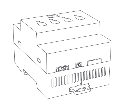
Wireframe
Product Overview
The DIN Rail Module (4 Channels) AW110K is a smart control module with low-voltage DC input and DIN rail mounting. It supports a maximum load of 16 A per channel and uses high-precision current transformers to independently monitor the current of each channel. The module features four independent channel control buttons and connects to the Aqara Distribution Box Gateway via an RS485 interface, enabling stable and long-distance on/off control. It also features over-temperature and overload protection to ensure safe operation. When used with a compatible automation system, the module supports remote control, scheduled operation, real-time energy consumption monitoring, and energy usage statistics. It can also work with other smart devices to create a variety of automated scenarios.
Sales Information
| Version | Sales Region |
|---|---|
| China Version | China Mainland |
| Overseas Version | European Union |
Installation Instructions
Installation Conditions
Installation tool: Connecting cable (twisted-pair cable or AWG 28 electronic wire is recommended; to be prepared separately)
Installation Precautions
- Before wiring, be sure to disconnect the main power supply and ensure that the device is completely powered off to avoid electrical accidents such as electric shock or short circuits. Before wiring, insert the wiring terminals provided in the accessory bag into the interfaces on the bottom of the device for subsequent wiring.
- It is recommended to use cables that comply with electrical installation standards. Leave approximately 8 mm of stripped wire length according to the terminal specifications. The recommended wire outer diameter is 1.05 mm. After wiring, make sure that all wires are securely inserted into the terminals and firmly fastened.
Installation Steps
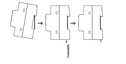
Step 1: Install the Module
After disconnecting the main power supply, install the DIN Rail Module (4 Channels) on the DIN rail. For convenience, the "DIN Rail Module (4 Channels)" is referred to as the "module" below.
Step 2: Connect the Gateway to the First Module
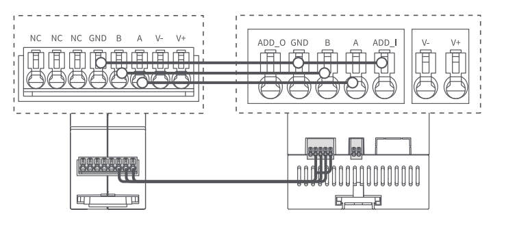
Connect terminals A, B, and GND of the Aqara Distribution Box Gateway to the corresponding A, B, and GND terminals of the first module, respectively. Except for the GND terminal of the first module, which needs to be connected to its own ADD_I terminal, the GND terminals of the other modules do not need to be connected.
Step 3: Connect the Communication Cables Between Modules
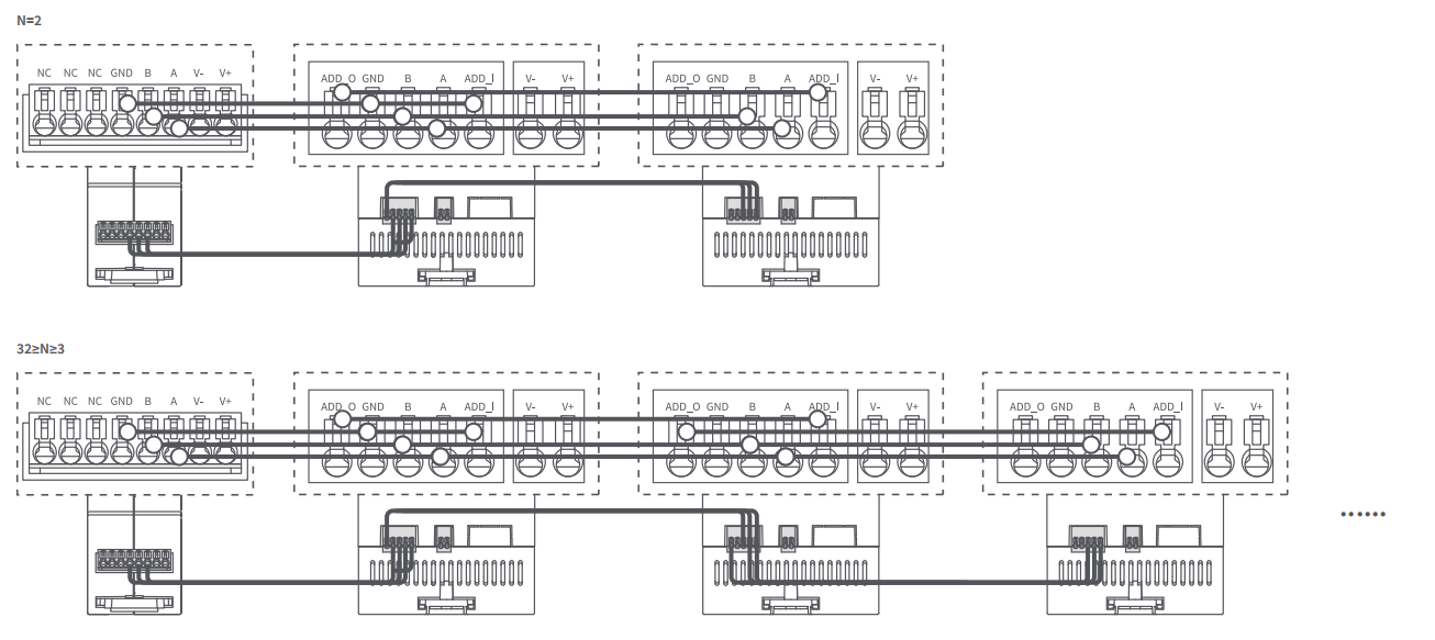
Multiple modules are connected in a daisy-chain configuration, supporting up to 32 modules in total.
- ADD_I / ADD_O connection: Connect the ADD_O terminal of the first module to the ADD_I terminal of the second module, and connect the ADD_I terminal of the first module to its GND terminal. Then connect the ADD_O terminal of the second module to the ADD_I terminal of the third module, and so on. The ADD_O terminal of the last module does not need to be connected and should be left unconnected. ADD_I and ADD_O are the input and output ports for the module communication signals, used to identify the connection sequence between modules.
- A / B connection: Connect the A and B terminals of each module in sequence using a daisy-chain configuration. Ensure that A is connected to A and B is connected to B. Do not cross-connect the A and B terminals.
Step 4: Connect the Loads
Connect the four load wires, such as those for lights, power outlets, or other controlled devices, to the corresponding load terminals of the module.
After completing the wiring, make sure that all load wires are securely connected and that there are no loose, exposed, or incorrectly connected wires.
Step 5: Power-On Check
After confirming that all wiring is correct, switch on the main power supply. Check whether the module is receiving power properly and whether the indicator light enters the normal operating state. If any abnormality is detected, immediately disconnect the power supply and check the wiring. The device must be connected to an external overcurrent protection device rated at 16 A.
Power Wiring
Connect the power supply's V- and V+ terminals to the corresponding V- and V+ terminals on the gateway and module, respectively.
Connect the V- and V+ terminals between the gateway and each module in sequence using a daisy-chain configuration. Ensure that V- is connected to V- and V+ is connected to V+. Do not cross-connect the terminals.
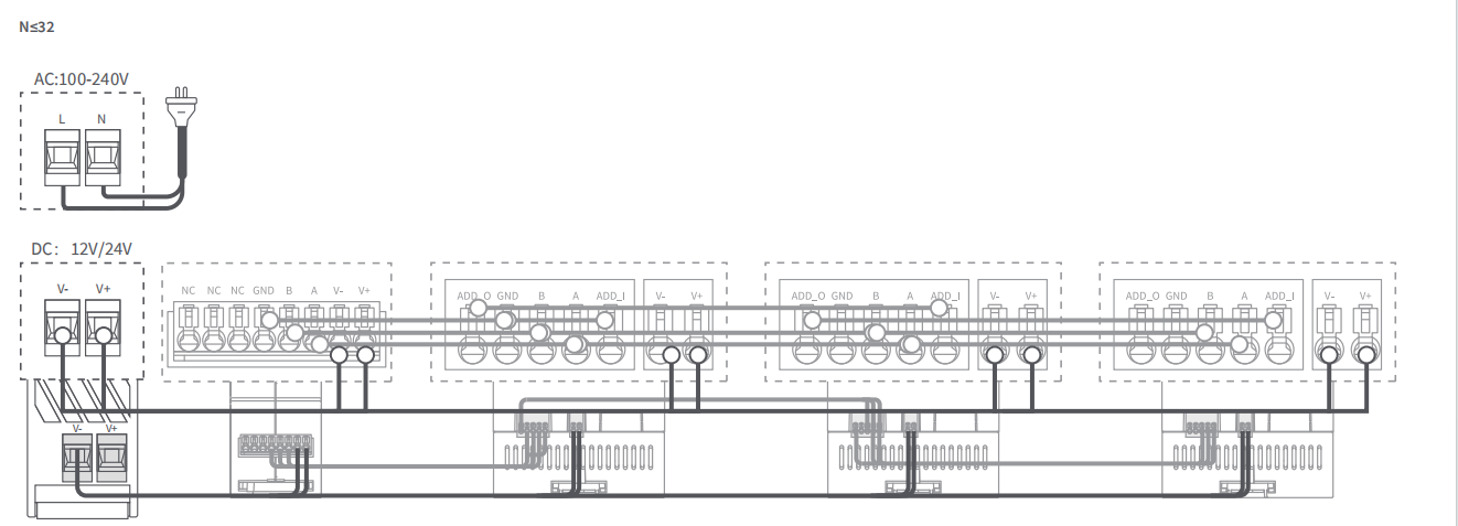
After confirming that the module communication cables, power cables, and load wires are all correctly connected, connect and switch on the main power supply to put the device into normal operating mode.
If the module indicator light behaves abnormally, the loads cannot be controlled, or the device cannot be recognized, immediately disconnect the power supply and check whether the A, B, GND, ADD_I, ADD_O, V-, V+, and load terminals are correctly connected.
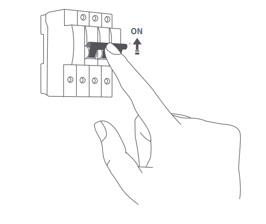
Device Pairing
- Connect this module to an Aqara Distribution Box Gateway with an RS485 interface.
- Refer to Aqara Hub Device Integration to connect the Aqara Distribution Box Gateway to Aqara Studio.
- Refer to Aqara RS-485 Device Integration to connect this module to Aqara Studio.
Product Features
Product Feature Description
Four-Channel Switch Control
The DIN Rail Module (4 Channels) can independently control up to four circuits, making it suitable for the separate control of lights, power outlets, and other electrical devices. Users can control each channel individually through local or remote on/off control according to their needs. Remote control requires an Aqara Distribution Box Gateway. The gateway must be connected to Aqara Studio for configuration and operation.
Interlock Switch
The interlock switch function prevents designated channels from being turned on simultaneously, avoiding conflicting operations and improving the safety and reliability of the device.
This function is suitable for devices or circuits that require interlocking control, such as curtain motors, forward/reverse motors, or other applications where two circuits must not be powered simultaneously.
Users can configure the channels to be interlocked in Aqara Studio according to their needs.
This function requires an Aqara Distribution Box Gateway and must be configured through Aqara Studio. Click Switch Interlock Enable and assign the same write value to the two circuits that need to be interlocked (e.g., 6, 66, or 88).
Power-On State (Power-Off Memory) Settings
The Power-On State (Power-Off Memory) function allows users to set the switch state of the device when power is restored after a power outage. This reduces the need for manual intervention and ensures that the device resumes operation as expected.
The available power-on states include:
| Power-On State | Description |
|---|---|
| Power-On Memory | Restores the switch state before the power outage |
| Power-On | Automatically turns on the channel when power is restored |
| Power-Off | Keeps the channel off when power is restored |
The default setting is Power-On Memory.
This function requires an Aqara Distribution Box Gateway and must be configured through Aqara Studio.
Current and Power Measurement
The device supports real-time monitoring of the current and power consumption of each channel, helping users understand their electricity usage.
Users can view the relevant data through Aqara Studio to help determine whether the device is operating properly and optimize energy management.
To estimate power consumption, the corresponding voltage value must first be configured on the Voltage page.
This function requires an Aqara Distribution Box Gateway. After connecting the gateway to Aqara Studio, users can view the relevant data in Aqara Studio.
Over-Temperature and Overload Protection
The device supports over-temperature and overload protection. When an abnormal temperature or current is detected, the device automatically activates the corresponding protection mechanism to reduce the risk of device damage and electrical hazards.
Some protection strategies must be configured through Aqara Studio. Protection strategy configuration and alarm notifications require an Aqara Distribution Box Gateway and Aqara Studio.
Overload Protection
The device monitors the load status through current detection. When the current detected on any channel exceeds the configured load range, the device automatically disconnects the corresponding relay and enters the safety protection state. A danger alarm notification is also sent to the user.
The overload protection strategy supports the following settings:
- Single-channel overload -> single-channel power-off.
- Single-channel overload -> all-channel power-off.
If no setting is configured by the user, the default strategy is single-channel overload -> single-channel power-off.
Over-Temperature Protection
The device monitors its operating status through an internal temperature sensor. When the internal temperature exceeds 65°C / 149°F, the device automatically disconnects the relays and enters the safety protection state. A danger alarm notification is also sent to the user.
When over-temperature protection is triggered, all four relays are forcibly switched off to ensure device and electrical safety.
Safety Protection State
When the device is in the safety protection state, it limits the output of the corresponding channel or all channels to prevent the abnormal condition from escalating. After the device returns to normal operating conditions, press any power button to exit the safety protection state.
Indicator Lights and Buttons
Fast flashing:
- Over-temperature: Fast flashes 3 times, then remains solid for 3 seconds.
- Overload: Fast flashes 5 times, then remains solid for 3 seconds.
Pairing Indicator
| Color | Status | Description |
|---|---|---|
| Blue | Fast flashing | Device powering on/device pairing/device discovery/device removal |
| Blue | Solid on | Device online |
| Red | Fast flashing | Device offline |
| Red | Solid on | Over-temperature/overload/pairing timeout |
Switch Indicator
| Color | Status | Description |
|---|---|---|
| Blue | Fast flashing | Over-temperature/overload |
| Blue | Solid | Normal |
Button Instructions
Pairing Button
| Button Operation | Description |
|---|---|
| Double-click, then press and hold | Reset pairing |
| Click 10 times consecutively | Restore factory settings |
Press and hold: Press and hold for more than 5 seconds.
Switch Button
| Button Operation | Description |
|---|---|
| Single-click | Turn on/ turn off/exit safety protection state |
Precautions
- This product is a low-voltage input control device designed for installation inside a distribution box. Installation, wiring, commissioning, and maintenance must be performed by a qualified electrician or a professional with relevant experience.
- Before installation, wiring, or maintenance, always switch off the main power supply of the distribution box and confirm that the power has been completely disconnected to avoid the risk of electric shock or short circuit.
- This product is intended for use in dry indoor environments only. The distribution box should provide adequate protection against moisture and dust.
- Ensure that all wiring connections are secure and that the wires comply with applicable electrical standards. Loose connections or overloaded wires may cause overheating or damage.
- Avoid excessive temperatures inside the distribution box and ensure that the distribution box complies with applicable installation standards.
- Do not allow water, oil, or other liquids to enter the distribution box or the product, as this may cause damage or malfunction.
- Do not disassemble, modify, or bypass any safety protection functions of the product. All repairs must be performed by authorized professionals.
- This product is intended for centralized smart home control and energy management. The manufacturer shall not be held responsible for risks, system failures, or property damage caused by improper installation or misuse.
- The device must be connected to an external overcurrent protection device with a rated current of 16 A.
Automation Information
Supported Automation Actions
Four-channel ON/OFF/Toggle Control
Product Certification
- SRRC
- Product Quality Inspection Report
- CE
Troubleshooting
How do I handle network pairing failure?
After powering on the device, double-click the pairing button, then press and hold it for more than 5 seconds. Once the blue indicator starts flashing, try adding the device again.
Product Selling Points
Product Selling Point Description
- Four independent channels, powerful control: Four independent output channels, each supporting up to 16 A, enabling flexible control of high-load devices with reliable and safe operation.
- Precise metering, transparent energy use: Four independent current transformers provide accurate metering for each channel, allowing precise monitoring of current consumption (A).
- Power protection, safe and reliable: Real-time monitoring detects over-temperature and overload conditions. When an abnormality is detected, the output is immediately shut off and the device enters protection mode. Alarm notifications are also pushed to the app to help ensure electrical safety.
- Power failure memory, hassle-free recovery: Supports power-off memory, allowing users to customize the device behavior after power is restored, such as remaining off or automatically turning on, for greater safety and convenience.
- Professional wired integration, stable and reliable: Supports the Aqara wired protocol and provides stable integration with building automation systems (BAS) or smart gateways via the RS485 interface, meeting professional integration requirements.
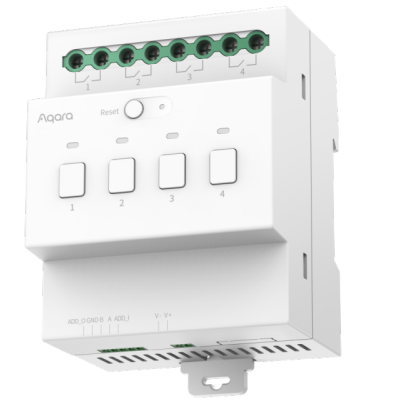
Product Image / Selling Point Poster
FAQ
Does the AW110K 4-Channel Control Module support third-party RS-485 protocols, such as Modbus RTU or BACnet MS/TP?
No. Third-party RS-485 protocols are currently not supported.
What are the advantages and disadvantages of the wired RS-485 protocol compared with wireless protocols such as Zigbee and Thread?
RS-485 is simple and reliable, and requires minimal maintenance once deployed. However, it requires pre-installation and wiring, making it more difficult to add new devices later.