Lighting Scene Controller AW100L
Lighting Scene Controller AW100L
Product Information
Basic Information
| Parameter | Description |
|---|---|
| Name | Lighting Scene Controller AW100L |
| Model Number | CJKZQ12LM |
| Product Type | Lighting |
| Barcode | 6978350350233 |
| SKU Code | AL240CNW02 |
| Product ID | A01624 |
Product Highlights
Key Features
- RS-485 Wired Communication: Adopts industrial-grade RS-485 bus with stable communication and anti-interference capability. Supports long-distance transmission and multi-device daisy-chain cascading. Combined with Zigbee wireless access, it balances reliability and flexibility.
- 4-Channel Output with Flexible Expansion: 4-channel SPI control output, each channel supports up to 100 IC pixels, total output power Max 480W. Supports multi-controller cascading, flexibly adapting to light box/light film projects of various scales.
- 16-bit High-Precision Dimming: 65,536-level grayscale (16-bit) fine dimming with silky smooth color transitions. Supports multiple PWM frequencies (4/8/12/16/20/24/32KHz), flicker-free for eye protection.
- Image/Video Scene Rendering: Supports uploading images/videos to generate dynamic lighting scenes, transforming light boxes into artistic canvases. One-click rendering of immersive scenes such as sunrise, blue sky, aurora, and more.
- AI Scene Generation: Supports AI scene generation capability, one-click generation of sunrise, blue sky, aurora, holiday, and other lighting scenes with differentiated advantages.
- Aqara Whole-Home Ecosystem: Deeply integrated with Aqara smart ecosystem. Based on Aqara Studio platform, supports sound-light linkage, automation scenarios, and multi-device linkage with door locks/curtains/sensors to build a complete smart home experience.
Product Image
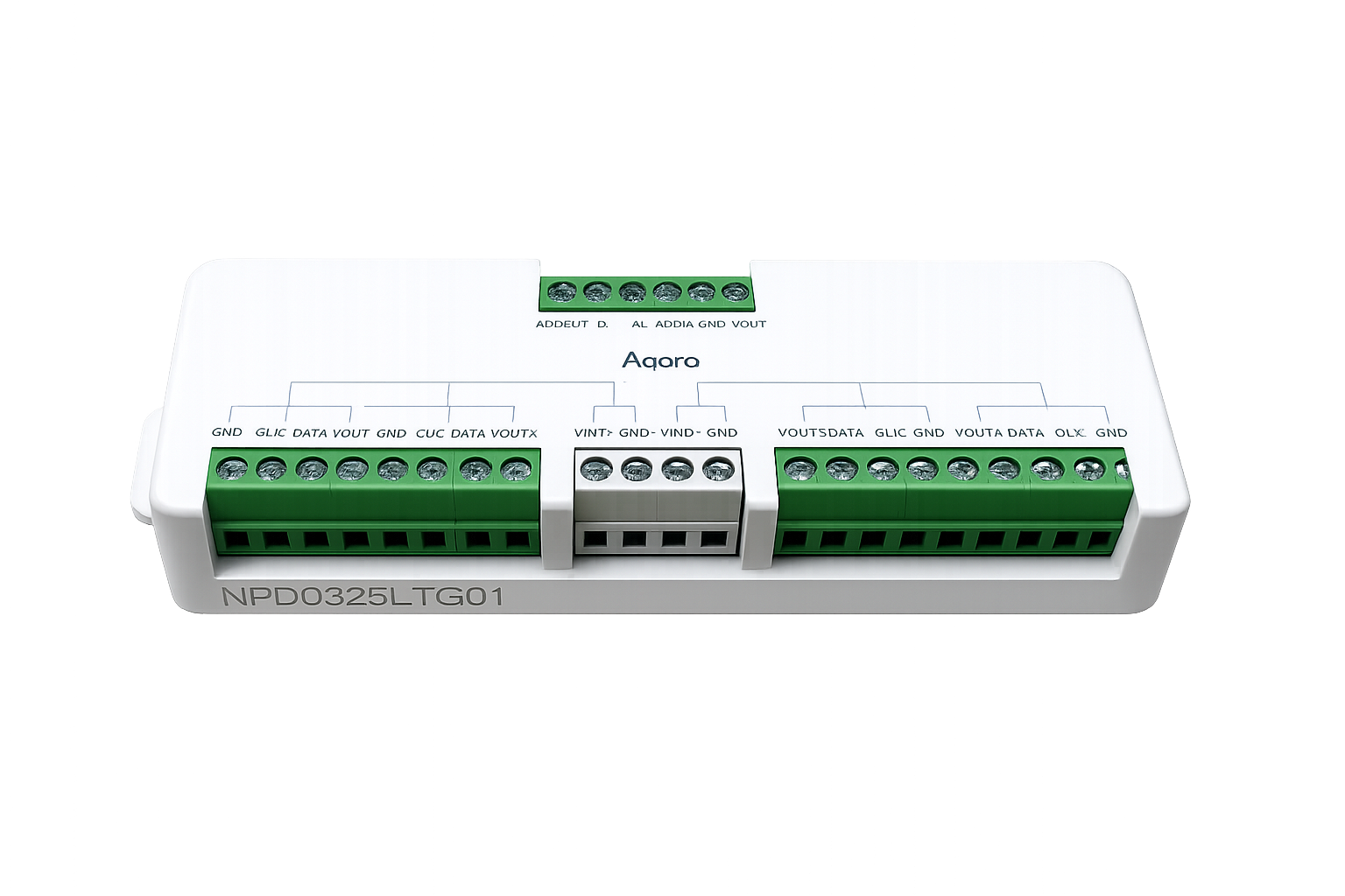
Product Specifications
Basic Specifications
| Parameter | Description |
|---|---|
| Product Dimensions | L154 x W46 x H21.2 mm |
| Operating Temperature | -10C ~ 40C |
| Operating Humidity | 0~95% RH, non-condensing |
| Input Voltage | DC 12-24V (dual input, VIN1/VIN2, each Max.10A) |
| Rated Dual Output | Vout1+Vout2: 12-24VDC, Max.10A; U-OUT=24V DC Vout3+Vout4: 12-24VDC, Max.10A; U-OUT=24V DC, Max.480W |
| Total Output Power | Max. 480W (four-channel output) |
| Signal Output | 4 SPI control ports, each supporting up to 100 IC pixels |
| Communication Protocol | RS-485 (requires use with Aries Gateway AX100M), Zigbee, Thread |
| Standby Power Consumption | <30mW |
| Protection Rating | IP20 |
| Mounting Method | Screw fixation |
| Package Contents | Controller x1, Screws x2, Wall Anchors x2, User Manual x1 |
Main Material
PC
Product Appearance
Wiring Diagram
The Lighting Scene Controller AW100L wiring ports are divided into three categories: Power Input Port x1, Output Port x2, and RS-485 Communication Port x1.
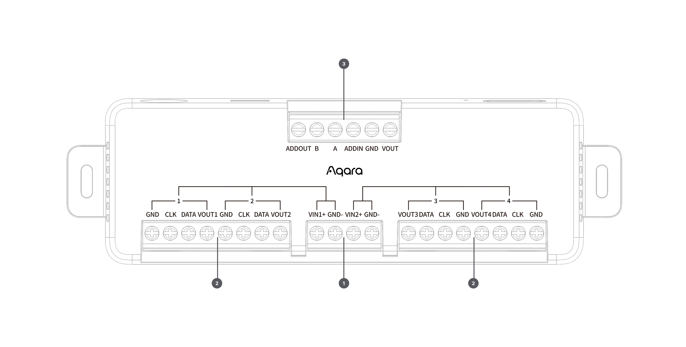
| No. | Port Name | Function Description |
|---|---|---|
| 1 | Power Input Port | VIN1+, VIN2+, GND- x2, connect to DC 12-24V power supply (Do not connect directly to mains) |
| 2 | Output Ports x2 | 4-channel SPI signal output (VOUT, DATA, CLK, GND), DATA connects to light board data input DI port, GND connects to light board negative terminal |
| 3 | RS-485 Communication Port | A, B (RS-485 signals), ADDIN, ADDOUT (address signals), VOUT, GND, for gateway connection and multi-controller daisy-chain cascading |
Terminal Wiring Instructions
-
Power Input Port:
No. Name Description Wiring 1 VIN1 Power Input 1 Positive + DC12/24V power positive + 2 GND Power Input 1 Negative - DC12/24V power negative - 3 VIN2 Power Input 2 Positive + DC12/24V power positive + 4 GND Power Input 2 Negative - DC12/24V power negative - noteVIN1: DC12/24V; VIN2: DC12/24V. Two independent power inputs. If power is connected to VIN1, output can only connect to VOUT1, VOUT2; if power is connected to VIN2, output can only connect to VOUT3, VOUT4.
-
Output Port:
No. Name Description Wiring 1 VOUT1/2/3/4 Power Output 1/2/3/4 Positive + Do not connect 2 DATA Data Signal Light board data input DI 3 CLK Clock Signal Do not connect (current light boards do not have CLK signal) 4 GND Power Output Negative - Light board input negative - noteSelect whether to connect CLK signal based on strip/board IC type. Current light boards do not have CLK signal, so do not connect.
When using double-shielded network cable, twist the shield copper wire together with the light board input negative wire and connect to controller output GND to enhance anti-interference capability.
-
RS-485 Communication Port:
No. Name Description Wiring 1 VOUT Power Output Positive + Gateway input positive+/Do not connect 2 GND Power Output Negative-/Signal Ground Gateway input negative-/Signal ground GND 3 ADDIN Address Input Signal First controller connects to GND; Controllers 2~n connect to previous controller's ADDOUT 4 A RS-485 Signal A Connect to Gateway/Previous controller's RS-485 Signal A port 5 B RS-485 Signal B Connect to Gateway/Previous controller's RS-485 Signal B port 6 ADDOUT Address Output Signal Connect to next controller's ADDIN noteThe first controller can power the gateway through VOUT and GND pins (connecting to gateway V+, V-). When the gateway uses Type-C power supply, VOUT can be left unconnected, but GND must still be connected to maintain common ground between controller and gateway signal ground.
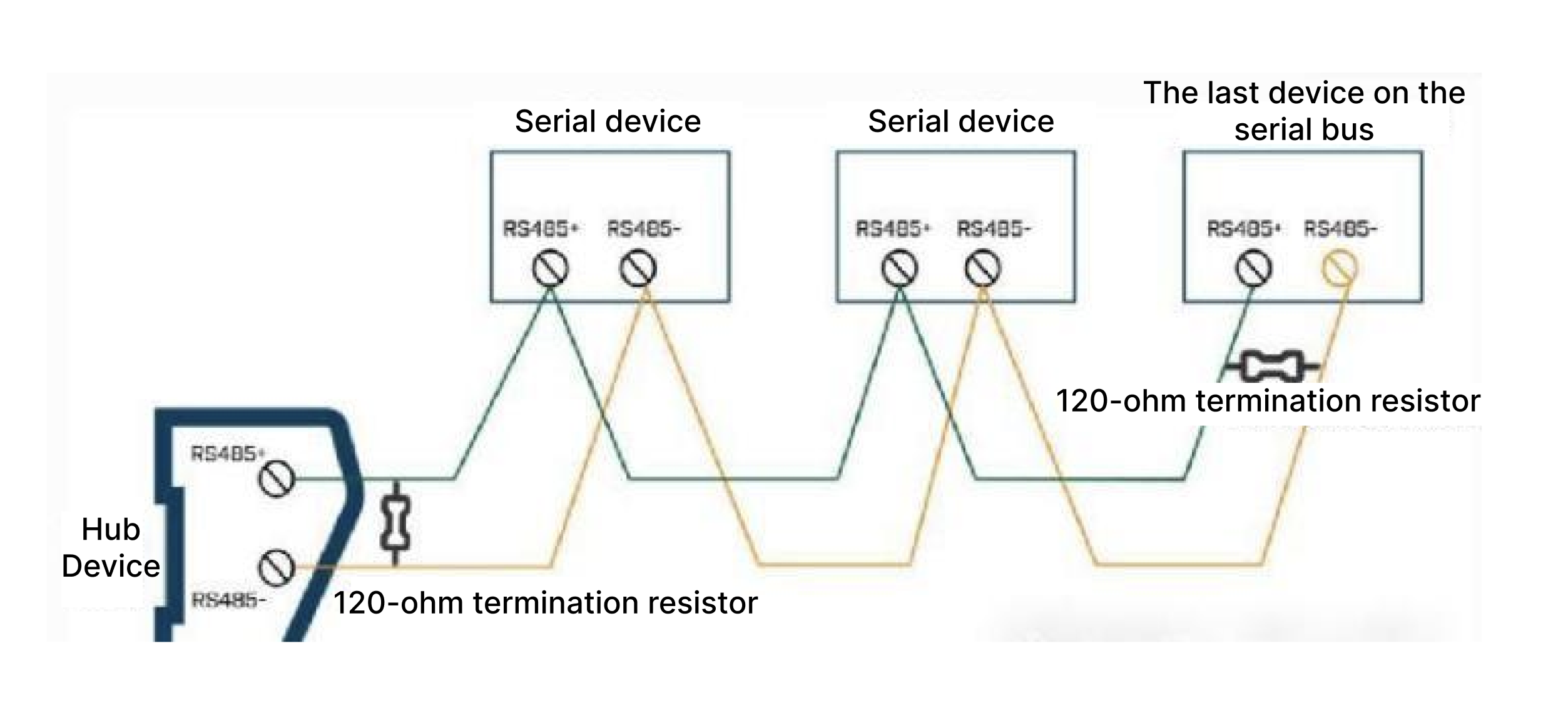
The gateway and controllers are connected via RS-485 daisy chain. The RS-485 A/B signals between the gateway and each controller must be wired in a hand-in-hand series without branching. The termination resistor DIP switches on the first and last controllers should be set to the right position (near the antenna port).
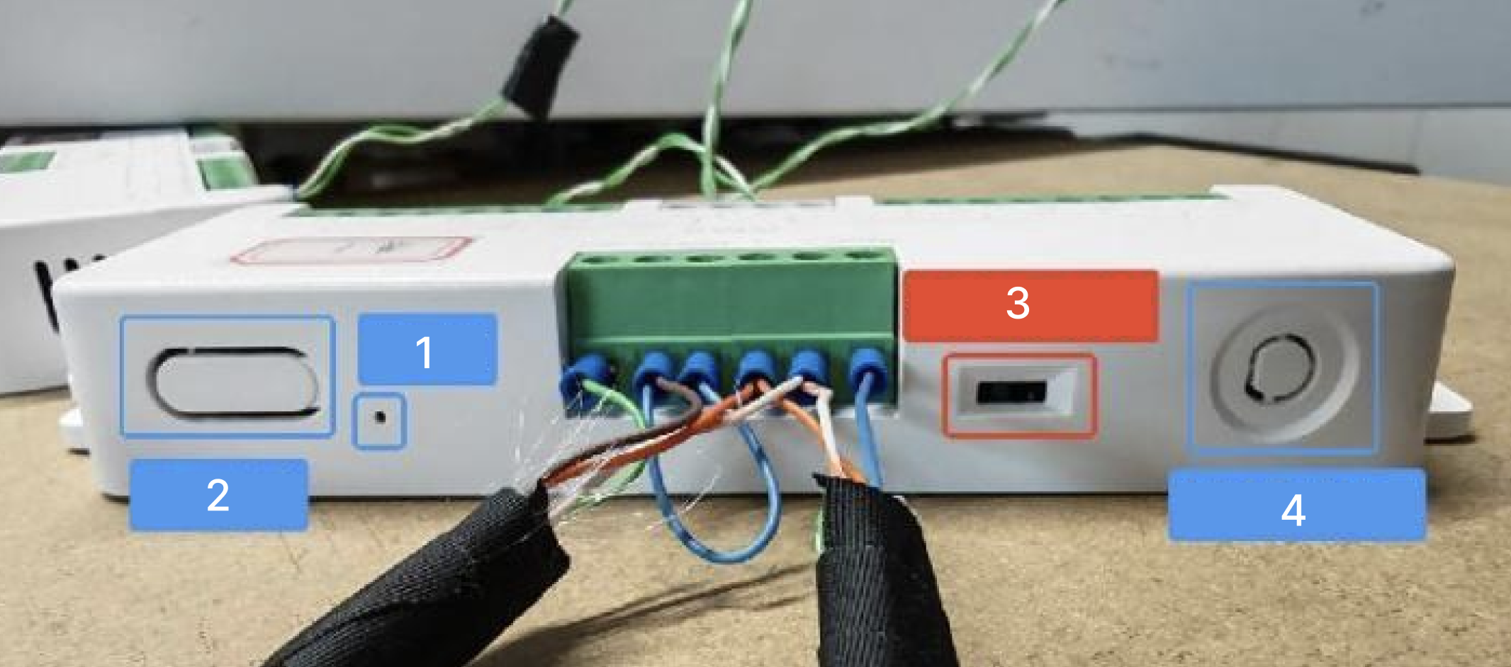
No. Name 1 Indicator light 2 Reset button 3 Termination resistor DIP switch 4 Reserved antenna port
Product Overview
The Lighting Scene Controller AW100L is the core control hub of Aqara's RS-485 scene lighting solution. It adopts industrial-grade RS-485 bus communication and requires use with AX100M. It can stably drive Pastel Light Board H1 (large board) and Pastel Light Module H1 (small board) and other SPI-RGBW tinted color light sources.
The controller provides 4-channel SPI control output, each channel supporting up to 100 IC pixels, with total output power up to Max 480W. It supports multi-controller RS-485 daisy-chain cascading, flexibly adapting to light box/light film projects of different scales. The controller uses DC 12-24V dual power input (VIN1/VIN2 each Max.10A), where VIN1 corresponds to VOUT1/2 output group, and VIN2 corresponds to VOUT3/4 output group.
Based on the Aqara Studio platform, controllers can be combined into light boxes, supporting switch, brightness, color control as well as static and dynamic scenes. It supports uploading images/videos to generate dynamic lighting scenes and AI scene generation, transforming light boxes into immersive artistic canvases. Combined with other Aqara smart devices, rich automation functions can be achieved.
- This device requires use with AX100M for full functionality support. Certain specific features are only supported within the Aqara ecosystem.
Light Box Installation Guide
Installation Conditions Confirmation
| Parameter | Description |
|---|---|
| Installation Environment | Indoor use (dry environment) |
| Installation Tools | Screwdriver, Crimping tool (VE tube terminals recommended), Wire cutters, Tape measure, Self-tapping screws |
| Supporting Equipment | AX100M, DC 12-24V constant voltage power supply (recommended Aqara power supplies: 100W-KGDY01LM, 150W-KGDY02LM, 200W-KGDY03LM, 300W-KGDY04LM), Pastel Light Board H1/Pastel Light Module H1 |
| Power Requirement | DC 12-24V (Do not connect directly to mains, must use with constant voltage switching power supply) |
| Communication Cable | Standard network cable (RS-485 communication cable) |
| Signal Cable | National standard RVVP double-shielded cable or Cat6 double-shielded network cable (control signal transmission cable) |
| Power Cable | Red/black power cable with wire gauge 1.5mm^2 or above |
Installation Precautions
This product is a low-voltage input control device. Installation, wiring, and commissioning must be performed by qualified electricians or professionals with relevant experience.**
- Before installation, wiring, or maintenance, ensure the power switch is turned off and confirm complete power disconnection to avoid electric shock or short circuit risks;
- This product is not a toy; keep away from children;
- This product is only suitable for indoor dry environments; the distribution box should have good moisture and dust protection performance;
- Ensure all wiring connections are secure and wires meet electrical standards to prevent overheating or damage caused by loose connections or wire overload;
- Do not install this product near heat sources;
- Prohibit water, oil, or other liquids from entering the product interior to prevent equipment damage or malfunction;
- Unauthorized disassembly, modification, or bypassing of safety protection functions is prohibited. All maintenance must be performed by authorized professionals;
- This product cannot be directly connected to mains; appropriate constant voltage control devices must be used;
- The termination resistor DIP switches on the first and last controllers should be set to the right position (toward antenna port direction); same applies for single-controller setups;
- It is recommended to use VE tube terminals and crimping tools to crimp all wires for the same port together for easier wiring management;
- The distance from the signal output end to the first light board in the light box should not exceed 6m (with double-shielded cable communication);
- Signal wires and negative wires should be routed together, maintaining equal length as much as possible to reduce signal interference;
- The gateway and controllers are connected via RS-485 daisy chain; A/B signal wires must be hand-in-hand series connection without branching;
- If the light box uses multiple power supplies, connect all 24V negative outputs from all power supplies within the light box system together to ensure common ground for each power supply and light board signal, equalizing zero potential and reducing interference. For multiple light box systems under the same gateway control, it is also recommended to connect all power output negatives together.
Light Box Equipment Quantity Calculation and Layout Planning
Calculate Required Number of Light Boards Based on Light Box Dimensions:
-
Recommended internal depth of light box (distance from LED lens surface to light film): 10cm, controlled within 8-12cm range;
-
Maximum recommended distance between light board and light box inner frame (light film edge): 4cm, otherwise dark zones will appear;
-
Layout at 8 boards per square meter; light board dimensions: 496mm x 296mm, with 2mm tolerance per side, gaps exist;
-
If light box dimensions are not multiples of 500mm x 250mm, appropriately increase spacing between light boards (recommended not exceeding 3cm), otherwise obvious dark zones will appear;
Calculate Required Number of Power Supplies and Power Distribution Based on Light Board Count:
- Maximum power per light board: 36W, calculate with 40W power reserve when determining total power supply quantity needed for the entire light box;
- To reduce signal interference and ensure lighting quality, please use Aqara power products: 100W Power Supply - KGDY01LM, 150W Power Supply - KGDY02LM, 200W Power Supply - KGDY03LM, 300W Power Supply - KGDY04LM;
Plan Light Board Signal Entry Point Position and Power Reinjection Position Based on Light Box Dimensions and Light Board Layout, Signal and Current Flow Direction, Calculate Required Number of Controllers:
-
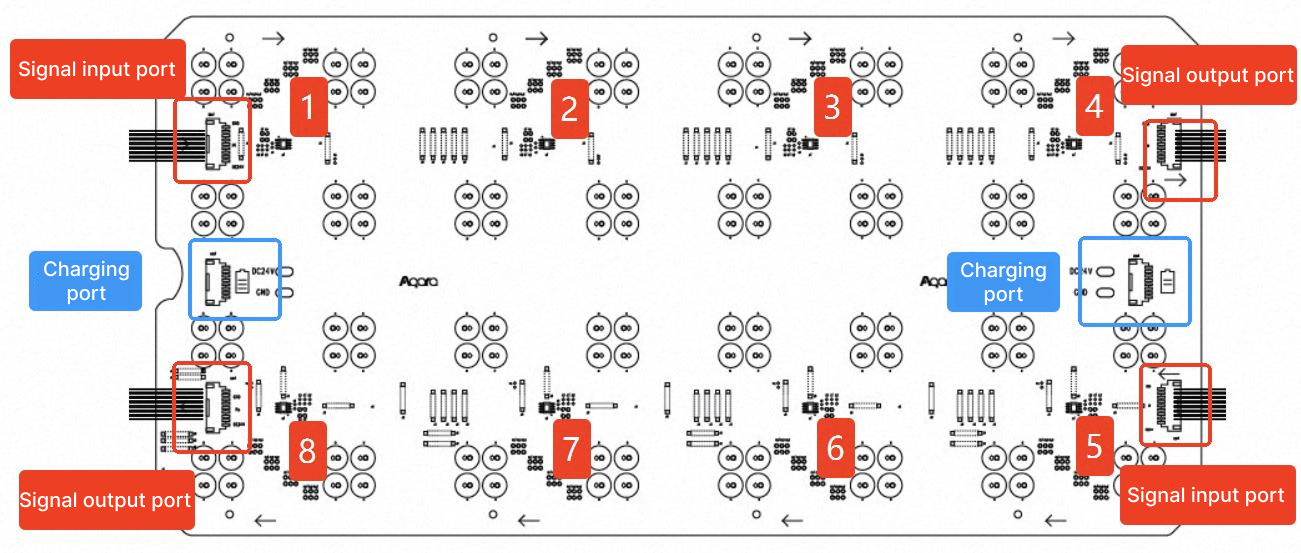
Light board orientation should be based on the power reinjection notch, arranged in uniform direction. Use signal input port 1 as the starting entry point. If light boards in the same row are arranged in reverse direction, short circuit will occur after connection;
-
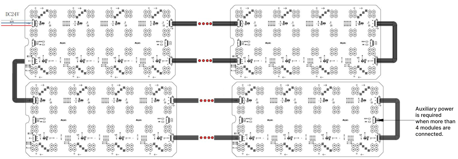
Each controller has 4 SPI control ports, each SPI controls 100 ICs. One large light board contains 8 ICs, so single channel can connect maximum 12 large light boards;
-
When series-connected light board supply voltage drops to around 23V, power reinjection is needed. Approximately every 4 large light boards require power reinjection. Entry point and reinjection position should preferably be on the same side of the light box for convenient wiring and management;
Light Board Fixing and Wiring
Use Self-Tapping Screws to Fix Light Boards onto Light Box Base Plate
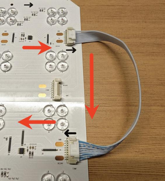
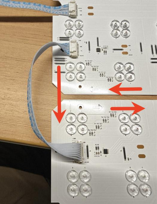
Use Included Connection Cables to Connect Light Boards
- Light board connection must follow adjacent direction to each IC position; skipping or interval ICs is not allowed, otherwise APP or Studio system cannot map IC positions correctly, causing image display errors.
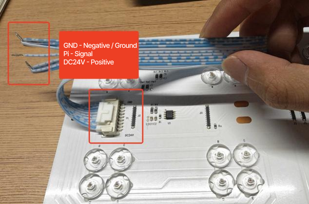
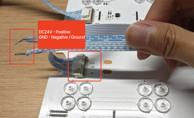
- Light board connection cables include: 1 9pin short inter-board cable, 2 9pin long inter-board cable, 3 9pin long signal cable, 4 8pin long power reinjection cable, as shown below:
- Use long signal cable for starting position signal entry; connect 24V positive/negative to power supply; connect signal and negative wires to controller (signal wire and negative wire should be routed together, maintaining equal length to reduce signal interference);
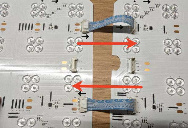
- Use short inter-board cables for horizontal light board connection between signal input/output ports;
- Use long inter-board cables for horizontal end light board self-connection on same side input/output ports; use long inter-board cables for vertical light board connection between signal input/output ports;
- Connect long power reinjection cable at reinjection port for boards requiring reinjection, then connect to power supply.
Power Supply Wiring
- It is recommended to select power cables with wire gauge of 1.5mm or above to prevent insufficient current-carrying capacity and excessive heat generation.
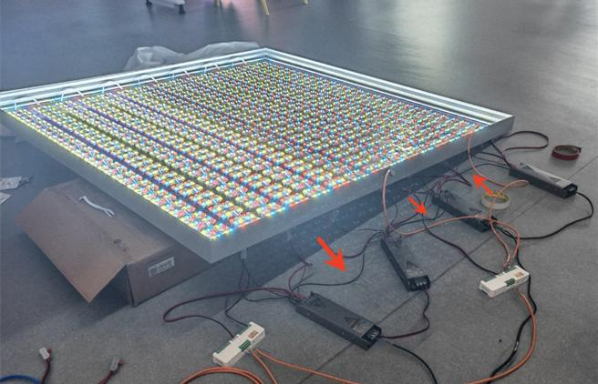
- Connect light board reinjection wires within the power supply range to the same power supply, not exceeding single power supply rating.
- If the light box uses multiple power supplies, connect all 24V negative outputs from all power supplies within the light box system together to ensure common ground for each power supply and light board signal, equalizing zero potential and reducing interference. For multiple light box systems under the same gateway control, it is also recommended to connect all power output negatives together.
As shown below:
Controller Wiring
Connect Power Supply, Gateway, and Controller According to Controller Wiring Instructions:
- Set the termination resistor DIP switches on the first and last controllers to the right position (toward antenna port direction); same applies for single-controller setups.
- It is recommended to use VE tube terminals and crimping tools to crimp all wires for the same port together for easier wiring management.
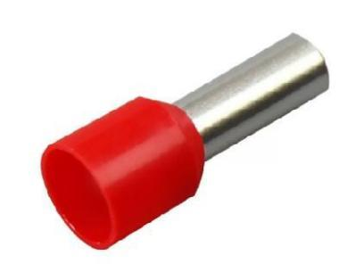
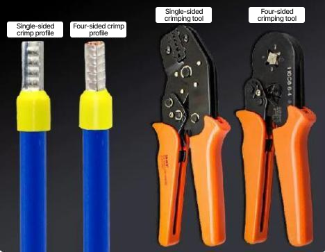
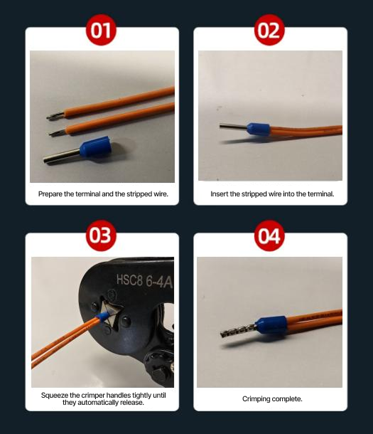
Connect Power Supply to VIN1-GND, or VIN2-GND, Either Group of Dual Power Input Ports to Power the Controller.
- Determine signal output channels 1/2/3/4, connect corresponding DATA port signal wires to light board data input DI port, and also connect light board GND to controller GND.
- With double-shielded cable communication, it is recommended to twist the light board GND wire together with shield layer copper wire into one strand before connecting to controller GND to enhance shielding capability.
Place Controller Near Light Box; Output Signal Wires Should Not Be Excessively Long;
-
With double-shielded cable communication, recommended distance from signal output end to first light board in light box should not exceed 6m;
-
See (Terminal Wiring Instructions) for specific wiring; wiring diagram shown below:
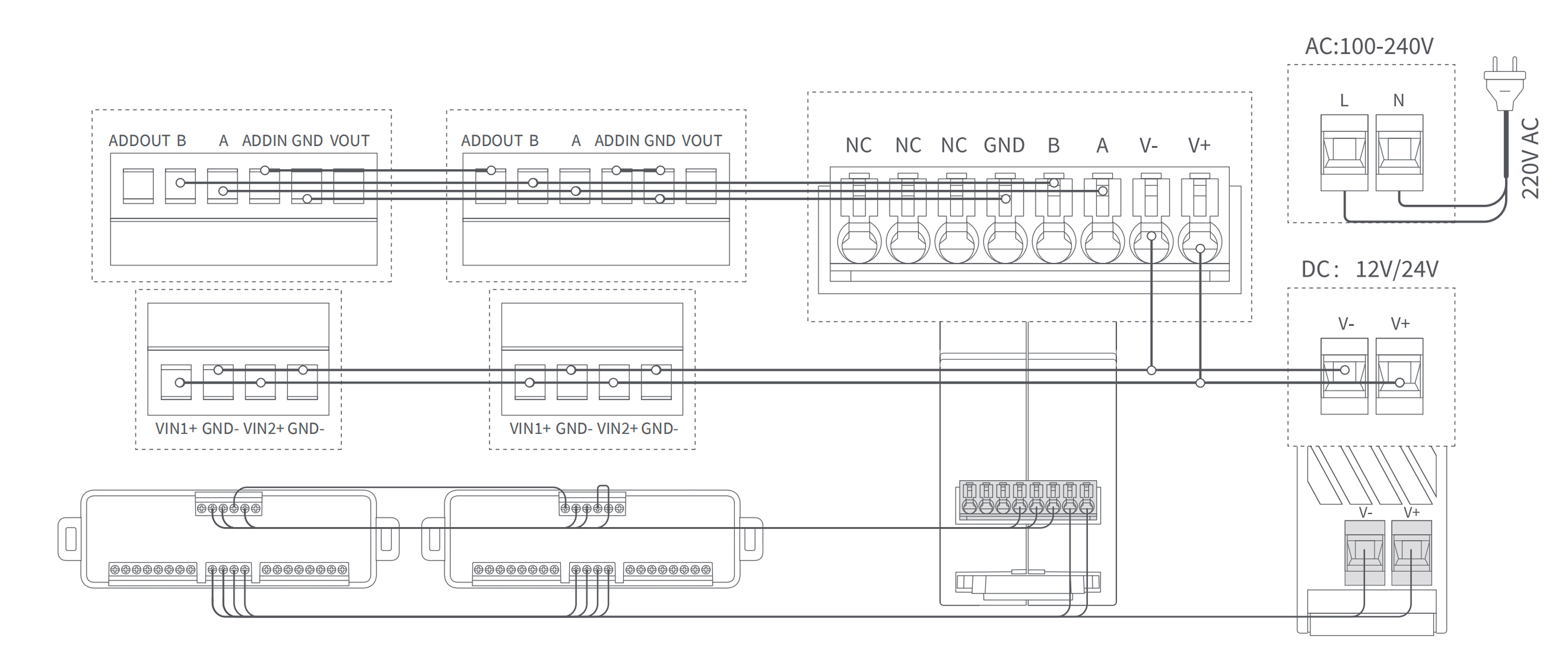
-
VE Tube Terminal Connected to Controller Port
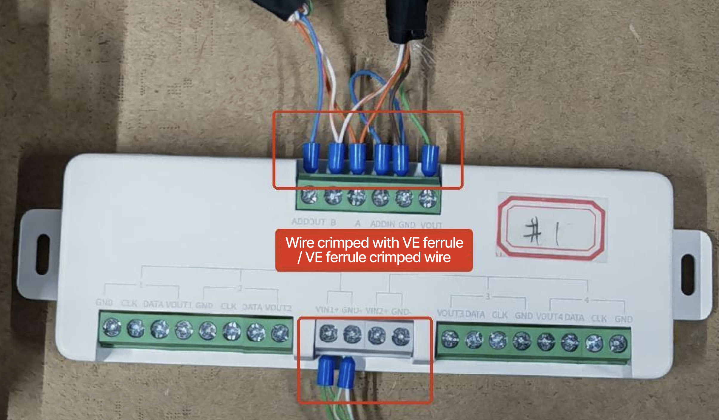
-
Gateway-Controller Wiring Diagram
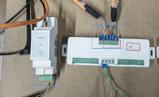
-
Controller-Controller Wiring Diagram
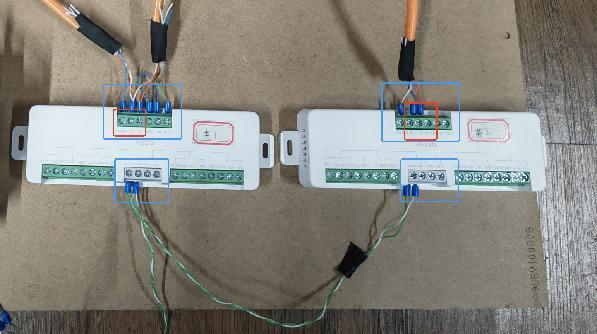
-
Complete Wiring Diagram
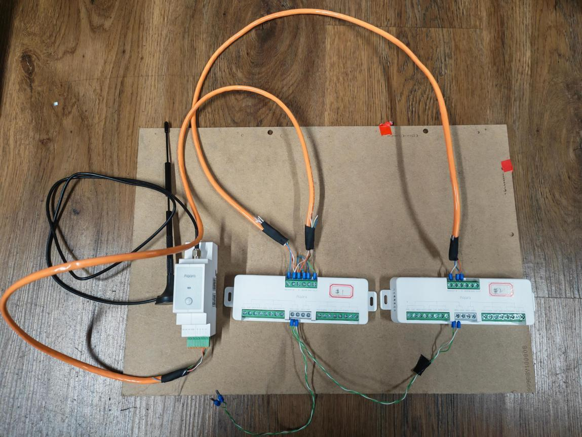
User Guide
Quick Setup
Power On Device
After completing connections, turn on power and confirm status of power supply, gateway, and controller; confirm all devices are working normally.
Add Devices
- Add DIN Rail Hub AX100M to Aqara Studio. For details, please refer to Aqara Hub Integration.
- Add Lighting Scene Controller AW100L to Aqara Studio. For details, please refer to Aqara RS-485 Device Integration.
Create Light Box
Create a light box device in Aqara Studio. For more details, please refer to Light Box Device Integration - Create Light Box Device.
The light box device should be configured as follows:
- Light Source Load Model: RGBCW Light Source
- LED Type: RGBW Tinted Color LED
- LED Protocol: Select SM5206E for Pastel Light Board H1; Select SM18635E for Pastel Light Module H1
Configure Sub-controllers
After successful creation, enter light box device configuration. In "Light Box Configuration", select the added RS-485 LED Strip Controller for "Sub-Controller-1". For details, please refer to Light Box Device Integration - Configure Sub-controllers.
Create New Scene (Image/Video)
- Click New Scene in "Scene Control" area:
- Static Scene: Upload image
- Dynamic Sequence: Upload video
- Save after upload to complete scene configuration.
For details, please refer to Aqara Device Configuration - Light Box Device.
Device defaults to Zigbee protocol for network joining. After device enters pairing mode, it can be added to Aqara Studio or Aqara Life App for use.
When device is not joined to network, upon powering on, light breathes twice and automatically enters pairing mode. Pairing time is 60s. If pairing time is exceeded, device can be power-cycled to re-enter pairing mode.
Product Functions
Basic Control
| Function | Description |
|---|---|
| On/Off | Supports overall light box on/off function |
| Brightness | Supports brightness adjustment |
| Color | Supports millions of color tones and wide-range color temperature adjustment (with quad-color light source) |
| Scene | Supports saving recommended scenes, static/dynamic scenes |
Scene Functions
| Function | Description |
|---|---|
| Recommended Scenes | Can save recommended image or video scenes for one-click recall |
| Image/Video Scene | Supports uploading images/videos to generate dynamic lighting scenes. Can set video frame extraction rate (per second, recommend 20 or 30 frames) and video hold time (recommend >=20ms), transforming light boxes into artistic canvases |
| AI Scene Generation | Supports AI scene generation capability, one-click generation of sunrise, blue sky, aurora, holiday, and other lighting scenes (based on Studio platform) |
| Tinted Color Static/Dynamic Lighting | Supports tinted color static/dynamic lighting effects (based on Studio platform) |
Configuration Options
| Configuration Item | Description |
|---|---|
| Power-On State Setting | Three modes available (default: Restore state at power-off) 1. Restore state at power-off: Maintain state before power-off after re-powering 2. Lights on after power-on: Turn on lights after re-powering 3. Lights off after power-off: Turn off lights after re-powering Note: Only supports image scene memory, restores original image display |
| Device Finder | Upon clicking, device flashes or beeps |
| Remove Device | After removing light box network joining status, synchronously remove from controlled LED strips; |
Maintenance
- Regularly wipe product surface with dry soft cloth to avoid dust accumulation affecting usage;
- Do not use chemical solvents to clean product;
- When not in use for extended periods, store in dry environment after disconnecting power.
Supported Gateway Information
This product requires use with AX100M for full functionality support, connected via RS-485 bus (A/B/GND/ADDIN). Gateway supports wired networking or WiFi wireless networking.
| Parameter | Description |
|---|---|
| Supported Gateway | DIN Rail Hub AX100M (RS-485 connection) |
Gateway has two power supply methods: 1 DC power supply V+/V- (can be powered by first controller's VOUT/GND pins); 2 Type-C adapter power supply. When using Type-C adapter power supply, gateway signal ground GND must be connected to controller signal ground GND to maintain common ground.
Troubleshooting Guide
Issue 1: Device Cannot Be Added / Cannot Be Discovered
| Possible Causes | Solutions |
|---|---|
|
|
Issue 2: Certain Light Board and Subsequent Boards Not Lighting Up
| Possible Causes | Solutions |
|---|---|
|
|
Issue 3: Lighting Effect Scrambled / Image Mismatch
| Possible Causes | Solutions |
|---|---|
|
|
Issue 4: Unstable Control / Signal Interference
| Possible Causes | Solutions |
|---|---|
|
|
FAQ
What light sources does Lighting Scene Controller AW100L support?
Currently supports Pastel Light Board H1 (large board, ZCGSSGYB01LM) and Pastel Light Module H1 (small board, ZCGSSGYMZ01LM) tinted color light sources.
How many light boards can a single controller connect?
The controller has 4 SPI control ports, each controlling up to 100 ICs. Taking large boards as example (8 ICs per board), single channel can connect maximum 12 boards; in actual use, when series-connected board supply voltage drops to around 23V, power reinjection is needed (approximately every 4 large boards).
Can the controller be connected directly to mains?
No. Controller input voltage is DC 12-24V, must be used with constant voltage switching power supply (recommended Aqara power products); direct connection to mains is not allowed.
What gateway is required for use?
Must be used with AX100M, connected via RS-485 bus (A/B/GND signal wires). Gateway supports wired networking or WiFi wireless networking. In APP, add controller as Modbus sub-device of gateway.
Can multiple controllers be cascaded?
Yes. Multiple controllers are connected via RS-485 daisy chain (hand-in-hand series, no branching). Previous controller's ADDOUT connects to next controller's ADDIN. Termination resistor DIP switches on first and last controllers must be set to right position (toward antenna port direction) to ON.
How to use the controller's dual power input?
The controller has two groups of power input ports: VIN1, VIN2 (each DC12/24V Max.10A). If power input is connected to VIN1, output can only connect to VOUT1, VOUT2; if power input is connected to VIN2, output can only connect to VOUT3, VOUT4. Either group can be selected to power the controller.
How should light boards be laid out in a light box?
Recommended internal depth of light box: 10cm (range 8-12cm); maximum distance between light board and light box inner frame: 4cm; layout at 8 large boards per square meter; recommended spacing between light boards: not exceeding 3cm, otherwise dark zones will appear. Light board orientation should be uniformly arranged based on power reinjection notch.
Why is the image effect displayed on light boards scrambled?
Please check: 1 Whether controller channels and light board wiring direction configured in APP match actual wiring completely; 2 Whether light board connection follows adjacent direction to each IC position (skipping or interval ICs not allowed); 3 Whether light board arrangement direction is uniform (based on power reinjection notch).
How to troubleshoot when part of light boards is not lit?
When certain light board and subsequent boards are not lit, check if front-end wiring of that light board is loose causing poor contact, re-plug and confirm latch is pressed tight (feel resistance and hear "click" sound); simultaneously check if cascade count exceeds power reinjection requirement (approximately every 4 large boards need reinjection).
What other features does the device have?
Supports static and dynamic scenes, supports uploading images/videos to generate dynamic lighting scenes (can set frame extraction count and hold time), supports AI scene generation (based on Studio platform), combined with other Aqara smart devices can achieve rich automation functions.