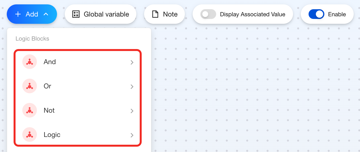
Logic Blocks
Screenshots in this guide may look slightly different from what you see on your device. Please follow the actual interface for reference.
Overview
In automation scenario configuration, if you want to determine whether to execute a step based on the combination results of multiple conditions, you need to use logic blocks, including: AND, OR, NOT, and Logical Operations.
The logic category includes the following blocks:
AND
Feature
Use the AND block when you need all selected device boolean states to meet the conditions before triggering a step.
Components
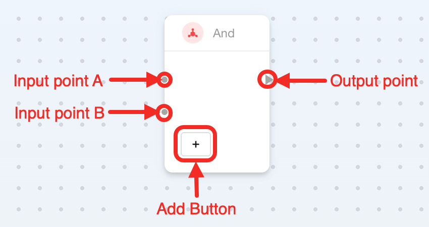
This is multi-point block, containing 2 input points (default), 1 output point, and 1 add button:
| Connection Point or Button | Required | Description |
|---|---|---|
| Input point A | ✔ | It connects 1 boolean Point Data. |
| Input point B | ✔ | It connects 1 boolean Point Data. |
| Add Button | ✘ | It adds more input points to connect more Point Data. |
| Output Point | ✔ | It connects to the step to be triggered when all conditions are met. |
How to Use
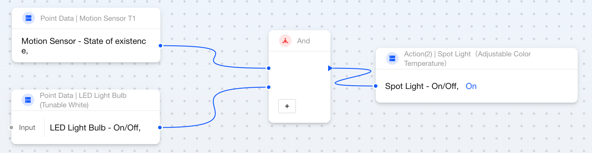
Here's how to use the AND block:
- Connect 2 boolean
Point Datablocks to the left side of the block. - Connect to
Actionblocks on the right side of the block. As long as all booleanPoint Datablocks aretrue, this step will be triggered.
The AND block usage steps described in this section do not include time restrictions. If you need to add validity periods for state changes, please refer to the timer blocks State Duration - Control Devices Based on Logical Operation Results.
OR
Feature
Use the OR block when you need to trigger a step when some of the selected device boolean states meet the conditions.
Components
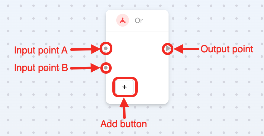
This block is multi-point type, supporting 2 input points and 1 output point by default, with 1 add button inside the block:
| Connection Point | Required | Description |
|---|---|---|
| Input point A | ✔ | It connects 1 boolean Point Data. |
| Input point B | ✔ | It connects 1 boolean Point Data. |
| Add Button | ✘ | It adds more input points to connect more Point Data. |
| Output Point | ✔ | It connects to the step to be triggered when any condition is met. |
How to Use
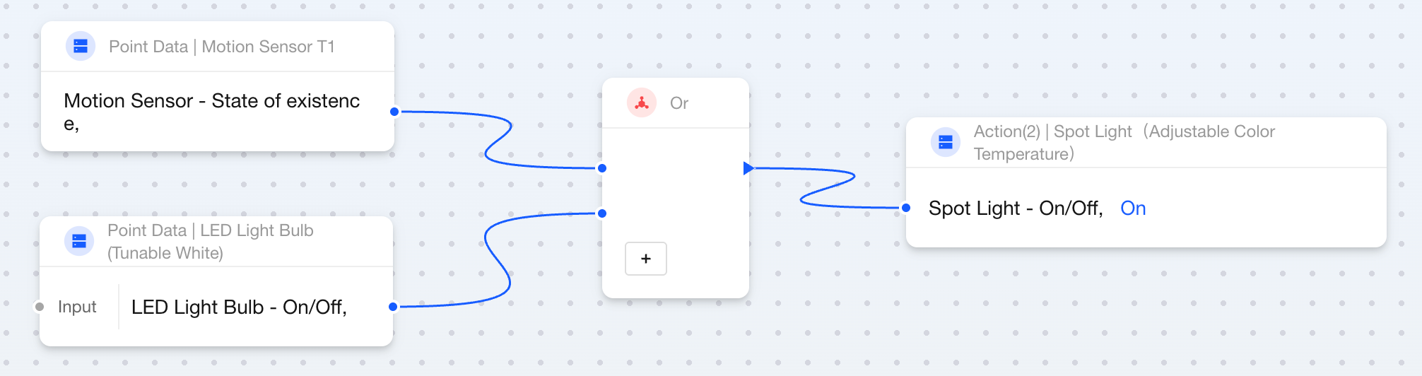
Here's how to use the OR block:
- Connect 2 boolean
Point Datablocks to the left side of the block. - Connect to the
Actionblock on the right side of the block. Only 1 booleanPoint Dataneeds to betrueto trigger this step.
The OR block usage steps described in this section do not include time restrictions. If you need to add validity periods for state changes, please refer to the timer blocks State Duration - Control Devices Based on Logical Operation Results.
NOT
Feature
Use the NOT block when you need to use the opposite value of a boolean state to control another state. This block will invert the boolean value of the input state and output it to the target state. For example:
- Switch state is true → outputs false, light turns off.
- Switch state is false → outputs true, light turns on.
Components
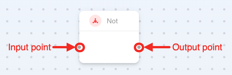
This is a dual-point block that requires no additional parameters:
| Connection point | Required | Description |
|---|---|---|
| Input Point | ✔ | It connects a boolean Point Data to pass a boolean value to this block. |
| Output Point | ✔ | It connects a boolean Point Data to receive the opposite boolean value of the input data. |
How to Use
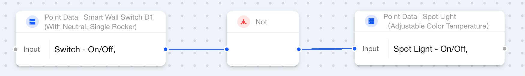
Here's how to use the NOT block:
- Connect a boolean
Point Datablock to the left side of the block to get the boolean value of that variable. - Connect a boolean
Point Datablock to the right side of the block to receive the opposite boolean value, thus controlling the device.
Logic
Feature
Use the Logic block when you need to compare two values to decide whether to execute an automation step.
This block supports the following comparison methods:
- Greater than
- Less than
- Equal to
- Greater than or equal to
- Less than or equal to
Components
This is multi-point block with 1 configurable parameter:
| Connection Point or Parameter | Required | Description |
|---|---|---|
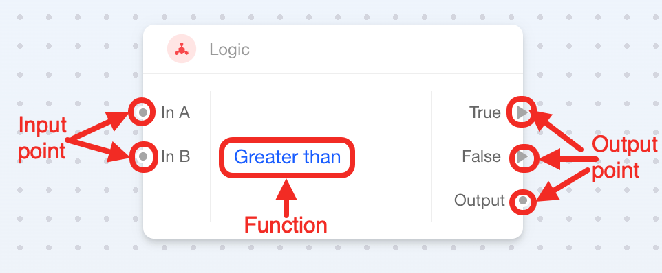
| In A (Input Point) | ✔ | Input A, the value to be compared. It can connect to 1 numeric Point Data or Numeric Variable. |
| In B (Input Point) | ✔ | Input B, the reference value, can connect to 1 numeric Point Data or Numeric Variable. |
| Function | ✔ | Select comparison method:
|
| True (Output Point) | One of the two required | It connects to the step executed when the condition is true. |
| False (Output Point) | One of the two required | It connects to the step executed when the condition is false. |
| Output (Output Point) | ✘ | It outputs the comparison result. |
How to Use
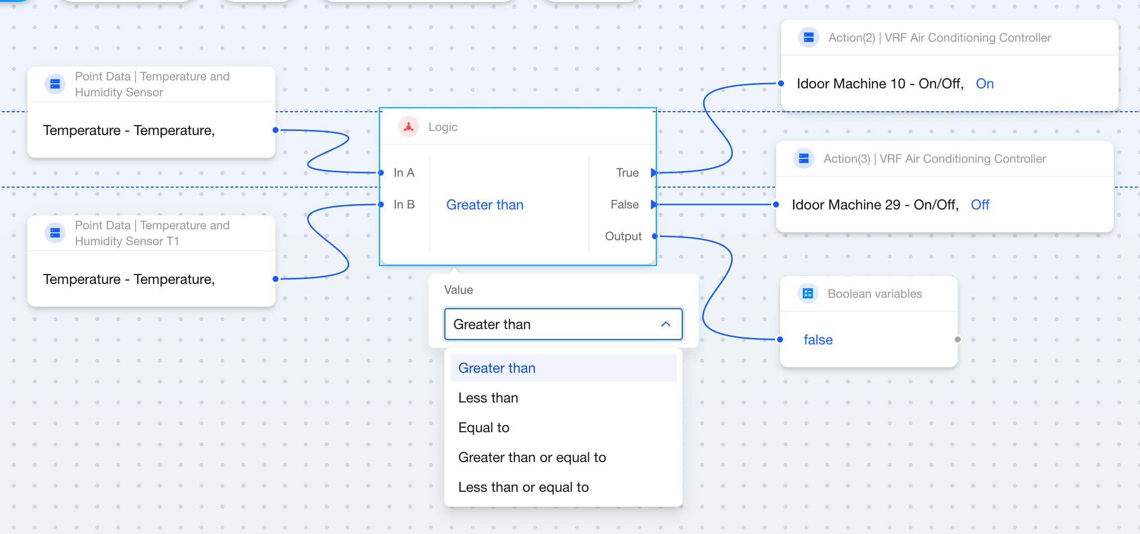
Here's how to use the Logic block:
- Connect two numeric parameters (Input A and Input B) to the left side of the block.
- Select a comparison method in the block (such as "Greater than").
- Connect the steps to be executed when judged as true or judged as false to the right side of the block.
- Connect a Boolean Variable block to the right side of the block to get the comparison result. This point can also connect to other blocks, such as AND and OR blocks.